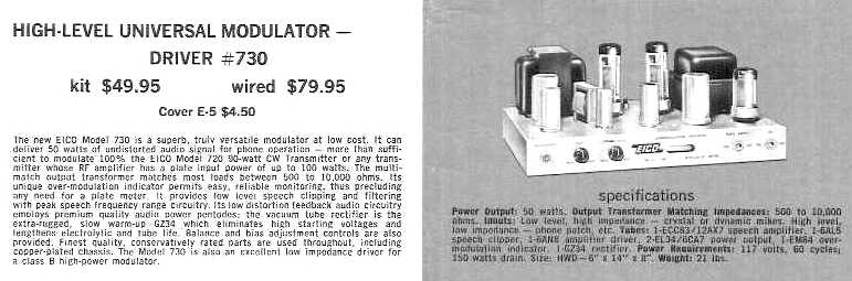
The Eico 730 50 watt modulator/ driver was introduced in 1958. According to the Eico ad in the 1959 Radio Amateur's Handbook, it was sold as a kit for $49.95 or wired at $79.95. The modulator cover, model E-5, was optional at $4.50.
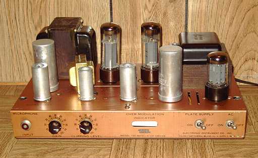
The modulator is designed for plate modulation of the matching Eico 720 transmitter or any transmitter with RF input power up to 100 watts or for driving a high power class B modulator. Like the 720 transmitter, the 730 featured a heavy copper-plated chassis and a nice low-profile design. The eye tube is used to monitor modulation levels. The octal socket on the rear panel includes the modulation transformer secondaries for matching various impedances from 500 to 10,000 ohm.
Tubes include a 12AX7 preamp, 6AN8 amplifier-phase inverter, 6AL5 speech clipper, a pair of 6CA7/ EL34 in push-pull, an EM84 eye tube, and a GZ34 / 5AR4 rectifier. The circuit is class AB1 with fixed bias.
The plate B+ of the 730 can be controlled remotely at the 720 or other transmitter as well as by a front-panel switch. Connection is by cable and plugs for the rear panel octal sockets. The 730 octal socket does NOT provide a chassis ground conection. The manual clearly states that a separate ground connection must be provided between the modulator and the transmitter when the two are connected. This is VERY important. Failure to provide the separate ground cable can place high voltage between the two chassis when using the remote control feature.
Repairs
The manual is available for download from BAMA in djvu format. I reviewed the schematic and did the usual safety checks, making sure the fuse was proper, checking for any power line to chassis leakage, and checking the power transformer for proper voltages. I reformed the electrolytics slowly with an external power supply.
One of the questions that arises with kit-built sets was knowing if it ever worked properly. I found a couple of bad solder joints and one resistor and an electrolytic ground that had not been soldered. Tie points with two three wires or component connections are suspect. Sometimes the terminal is soldered but not all of the wires. I also corrected several tube socket connections that were too close to neighboring connections, in one case having to remove and resolder a resistor to move it away from nearby connections.
With the GZ34 rectifier removed from its socket, I confirmed that the bias supply was working and preset it to -43 volts as stated in the manual. I also preset the balance control for the cathode current as stated in the manual.I connected a 5000 ohm audio output transformer and speaker to the 5K ohm connections on the rear panel octal socket. This was so I could test the modulator with a proper load as an audio amp and hear the quality of the audio through the speaker.
Modifications.
I then reinserted the rectifier and powered the modulator. I balanced the cathode current for the output tubes. I noticed a bit of color on the plate seam of one of the EL-34's. Using the chart in the manual, a comparison of the expected voltages on the plates and grids showed the plates and the main B+ a bit high and the grid voltages a bit low. I ended up changing the selenium rectifier for the bias supply to a 1N4007 diode. This change allowed a proper range for the fixed bias supply. I also switched the tap on the power transformer to the 125 volt primary tap (black and green wire) in place of the 117 volt primary tap (black and red wire). This change is discussed in the manual although the taps are not shown on the schematic. The change reduced the B+ a bit and of course the voltages on the EL-34 plates. The electrolytics in the modulator are rated at 500 VDC because even with only 117 VAC input, the main B+ is 475 volts at the rectifier according to the manual. The electrolytics should not be replaced with 450 volt units.
After the changes, the EL-34's were drawing somewhat less power on my AC input ammeter. Given the expense of these tubes and the increase in AC line voltage since 1958, the change to the 125 volt tap is more than appropriate. With the 121 volts at my AC outlet, the measured B+ was 480.
I traced a source of hum to the 5 Henry audio choke used in the clipping circuit. The hum was very noticeable with the speaker connected. It may not be noticeable in modulator service since there was nothing wrong with the circuit itself. Temporarily shorting out the choke eliminated the hum without affecting the preamp gain. On a hunch based on some experience with audio work, I reversed the choke wires. This resulted in greatly reduced hum.
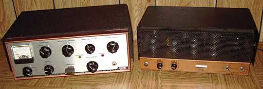
The matching Eico 720 transmitter was the previous item on the bench.