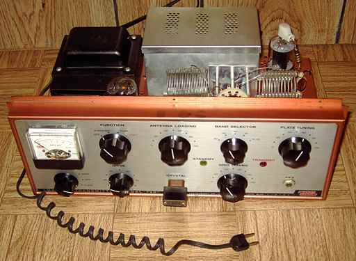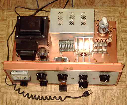

The Eico 720 transmitter was introduced in 1958. According to the Eico ad in the 1959 Radio Amateur's Handbook, it was sold as a kit for $79.95 or wired at $119.95. It is designed for the 80 to 10 meter ham bands (including 11 meters). It uses a 6CL6 as an electron coupled Colpitts crystal oscillator, a 6AQ5 as a Class A buffer multiplier, a 6AQ5 as clamp tube and a GZ34 / 5AR4 rectifier. Its final RF amplifier is a 6146 for 90 watts plate power input on CW. It featured a heavy copper-plated chassis and a nice low-profile design. A switch on the rear panel selects either a phono jack connection for an external VFO or a front-panel crystal. An accessory octal power socket is provided on the rear panel for powering a VFO, connecting an antenna relay, and/or an external plate modulator.
Eico sold a matching plate modulator, the 730 for $49.95 as a kit or $79.95 wired. The modulator cover, model E-5, was optional at $4.50.
Price comparisons - shopping in 1959
Heathkit offered the competing DX-40 rated at a bit less power, 75 watts, but with AM screen modulation built in, at a price of $64.95. The WRL Globe Chief 90, with specifications similar to the Eico 720, was already on the market a couple of years earlier at a price of $49.95. All of these transmitters were primarily aimed at the Novice class ham operator who was allowed to operate on CW only, with crystal control, at a maximum input of 75 watts on the lower ham bands. The slightly greater 90 watts and the provisions for an added VFO and/or modulator allowed an upgrade path after obtaining the General class license.


Repairs
I'm convinced this transmitter was never used. I was attracted to this set because its copper-plated chassis and overall cosmetics were in excellent condition. The chassis had never had the self-tapping screws for the base and the top cover installed. The seller was not the original owner did not know its origin. I pulled the new-looking Amperex Bugle Boy GZ34 rectifier that I felt was wasted in this set and put it aside for an Eico audio amplifier needing one. The manual is available for download from BAMA in djvu format. I reviewed the schematic and did the usual safety checks, making sure the fuse was proper, checking for any power line to chassis leakage, and checking the power transformer for proper voltages. I then subbed a 5U4GB rectifier. The electrolytics easily reformed.
One of the questions that arises with kit-built sets was knowing if it ever worked properly. The antenna coax under the chassis had been disconnected. Thinking the center insulation might have melted with too much heat from a soldering iron to a possible short, I cut the previous soldred portion off the cable and re-did the coax connection. I also found and fixed a bad solder joint on one side of the coil in the output Pi network.
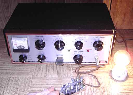
I used a grid dip meter to confirm that each ham band setting for plate tuning was possible. The octal accessory plug did not have a jumper for B+ power to the final. I soldered a jumper wire onto the plug. I then hooked up a light bulb dummy load, inserted an 80 meter crystal , connected a key, and followed the set-up procedure in the manual to try the transmitter. The grid current meter showed no response. I momentarily switched on the final but had no response on the meter or the transmitter.
Miswired meter, bad 6146, bad solder joints.
This immediately led me to check the meter. Using a VOM, I confirmed that the meter movement was fine. I checked the wiring to the meter and determined that the meter switch was miswired. Also, one side of the cathode current meter resistor was not soldered.
I also suspected a problem with the 6146. Although the Eico-labeled 6146 looked brand new, its plate cap was loose. It turned out to be broken at the glass seal. I checked the other tubes at this point with my TV-7 mutual-transconductance tube tester. That tester is usually a bit stingy on the meter but all of the other tubes tested as if they were new. I replaced the 6146 and retested the transmitter. This time, the transmitter loaded properly into the lamp dummy load. I found one more intermittent when loading the dummy bulb. The grounding solder joint of the plate tuning cap was cold-soldered and opened under load. Resoldering that joint completed the repairs.

"New Old Stock"
As noted, I doubt the 720 had ever been used on the ham bands. The set looks and feels like "new old stock". Evidence suggests the top and bottom covers were likely never installed because it never worked properly and that the 6146 was broken rather than burned out.
A Hallicrafters TW-2000 "World-Wide" was the previous item on the bench.