Hallicrafters TW-2000
The Hallicrafters TW-2000 "World-Wide" is another Zenith Transoceanic "clone" that is rather well-made. Like the later tube Transoceanics, it covers the standard AM broadcast and two continuous shortwave bands from 1.8 MHz to 8 MHz as well as the 16, 19, 25, and 31 meter international shortwave bands. The latter 4 are called spread bands, each covering a relatively narrow section of the short-waves thus eliminating the need for a separate "bandspread" function. Unlike the Zeniths, the TW-2000 also covers the VLF band from 180 to 400 KHz. The set was produced from 1952 to 1956. The original price of the TW-2000 in U.S. dollars was $149.95.
This particular set is a product of Hallicrafters - Canada Limited. A small attached store label indicates it was sold and serviced by Jeffrey Radio and Appliances in Nelson, British Columbia.
Comparison to the Transoceanics
Similarities
Like the Zenith Transoceanics, the Hallicrafters TW-2000 is quite sensitive for shortwave listening with just the built-in telescoping whip antenna if the radio is working well. The tube complement is the same as found in the typical Transoceanic and true clones with the expensive 1L6 converter, and the more common 3V4 audio output, 1U5 detector/AVC/ audio preamp, and two 1U4 for RF and IF amplifiers. Schematic, alignment and other information can be found in Sams Photofact 273-7. A manual and schematic are available from BAMA in djvu format. I found two obvious mistakes on the Sams schematic but none on the manual schematic.
Some differences
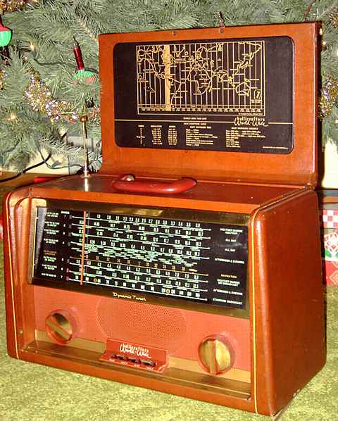
The TW-2000 with its brown leatherette case, its beautiful full-width slide rule dial, and its nice world map in the lid is a very handsome and desirable set.
The metal slide rule dial scale is covered with a large glass window mounted in a brass-color metal escutcheon. This has stood the test of time better than the plastic molded window and speaker grill of the Zeniths.
The TW-2000 has a larger 5X7 oval speaker.
The TW-2000 chassis is easier to remove for servicing. The knobs don't even have to be removed because the entire front of the radio comes out with the chassis.
The TW-2000 has the 180 to 400 KHz VLF band not found on the tube Transoceanics.
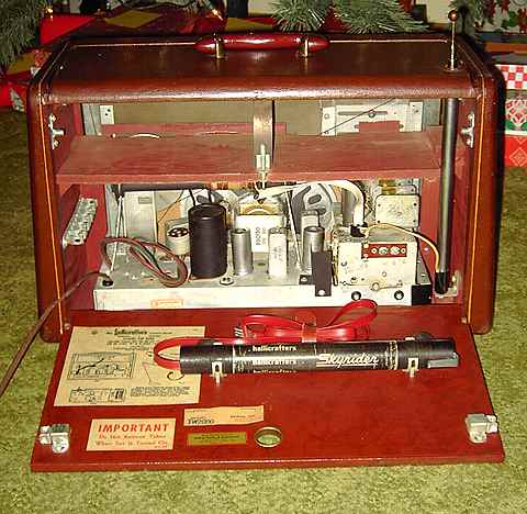
The TW-2000 uses a large fixed ferrite-rod antenna mounted on the chassis for reception of the VLF and broadcast bands. This ferrite-rod loopstick antenna replaces the large "Wavemagnet" removable loop antenna as found in the Zenith Transoceanics and the earlier Hallicrafters TW-1000 and 1000A. The removable Wavemagnet and similar loop antennas could be attached by suction cups to a window of an apartment, automobile, or railroad car to improve broadcast reception. In its place, the TW-2000 provides an encased second ferrite loopstick antenna for window mounting with suction cups or a metal clip. It comes complete with a length of red twin lead, the same color as that used for the Wavemagnets. The loopstick assembly has a built-in trimmer capacitor for peaking the antenna. Its smaller size makes the loopstick antenna more convenient to use than the larger loop Wavemagnets.
In comparing schematics, I noticed that every tube filament in the TW-2000 has a resistor in parallel across it. That reduces the problem of a filament-supply capacitor charging to full B+ in the event of a open filament or loose tube (and discharging that cap into the filaments if a new tube with a good filament is then inserted.) The resistors provide a full bleeder path.
I replaced the TW-2000's critical AC line capacitor with a proper unit rated for AC, something I routinely do in Zenith Transoceanics. At least the TW-2000 has the capacitor across the AC-line AFTER the power switch. In contrast, the Transoceanics, including the military models, have the cap always connected regardless of the switch setting. I have seen Transoceanics with that cap completely split open. I have always wondered about the wiring of that cap in the Transoceanics with a "what were they thinking" response and ALWAYS unplug a Transoceanic when it is not in use.
The TW-2000 uses a turret tuner which is an improvement in quality and stability versus the Zenith push-buttons. However, the turret makes the TW-2000 more difficult to align and the wiring to the 1L6 and the 1U4 RF amp more difficult to access.
The mechanical band-indicating marker for the Hallicrafters is a nice touch.
The TW-2000 tuning seems to have a fair amount of backlash. This may be because of the large slide rule dial and the more complicated dial string arrangement.
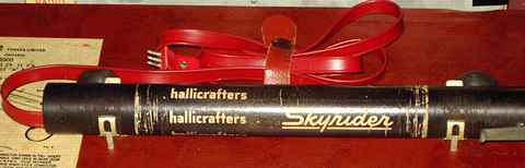
The last "Skyrider"
The name "Skyrider" had a long history with Hallicrafters. Skyrider speaks of the magic of radio and shortwave, bringing in distant stations by skip through the sky. It was the name given to the first Hallicrafters set, the S1, as well as to several later superheterodyne "Super" Skyrider models. The last receiver with the name of "Super Skyrider" was the SX-28A. The last use of "Skyrider" was the separate loopstick antenna in the TW-2000. I am convinced that Hallicrafters used the "Skyrider" moniker to compete with Zenith's equally imaginative "Wavemagnet" name.
Repair notes
I purchased this TW-2000 partly because of the set's very nice cosmetics. It worked on shortwave to some extent when purchased. I tested the 1L6 by seeing how low the voltage on the filament chain could go before the 1L6 oscillator dropped out at the set's highest frequency. I was pleased that the 1L6 would still function on the highest band with a minimum of 6.6 volts on the filament chain, a good result. There are two chokes in the filament chain whose resistance accounted for about half a volt so the tubes themselves were only seeing about 6.1 volts.
With 120 volts of AC input, the filament chain was measured at about 7.1 volts. The B+ was fine. I decided that the filament line was a bit low and modified this until the average was about 7.6 to 7.8 volts at the 120 line voltage. The string is designed for 9 volts according to the schematic, but I prefer to keep the chain at or just under 8 volts to increase the life of the delicate tube filaments, especially if the 1L6 is capable of operating with less. This also allows a bit of margin for those occasions when the AC input is higher than 120.
The set was nearly dead on the broadcast band. A quick look at the chassis showed the problem. The lead-in from the chassis-mounted loopstick antenna was missing. Apparently a previous owner had plugged and unplugged the chassis loopstick antenna so often in order to use the second movable loopstick that the wires to the chassis-mount loopstick had broken off. I plugged in the movable second loopstick antenna and the broadcast band was working. I found a matching plug for the chassis-mount antenna, attached a length of twin lead, and adjusted the chassis mount trimmer and the chassis-mounted broadcast-band coil for very pleasing sensitivity and performance on most of the broadcast band. The band cut out below about 650 KHz. I suspected that the tuning cap was shorting at that point. Sure enough, a close inspection of the cap and a simple bending of the outermost blade cured the shorting problem.
The wire connector to the telescoping antenna had also broken off and needed to be re-soldered.
Alignment
Aligning this set is not a simple task. The Sams Photofact and the manual each give the proper procedure. I did a frequency-counter check to see how close the bands were to the dial scale markings. The four highest shortwave bands are all at oscillator settings that are an IF frequency (455 KHz) under the markings. The VLF, Broadcast, and lowest shortwave band are all at oscillator settings that are an IF frequency higher than the dial.
Adjusting the oscillator slugs requires removing the speaker and the "baffle board" (lower front panel) to access the front of the turret bandswitch. None of the oscillator settings were off enough to justify removing baffle board. For a couple of the spread bands, I pulled the oscillator slug strip and adjusted it a bit, a quarter turn or less and invariably hit the mark or very close. The TW-2000 Run 2 apparently has a hole with a hole plug near the bandswitch knob that can be removed to allow oscillator adjustments without removing the baffle board.
The RF amp slugs are located on the back of the oscillator turret strips. Each antenna turret strip must be removed from the turret in order to access the RF amp slugs with a narrow non-metallic alignment tool. The antenna slug strips can be removed by bending the retainer spring holding the rear of each antenna slug strip. The slug strip for each band is labeled with a unique letter and number. The schematic in both the manual and the Sams Photofact has the cross-referece for band number and the code numbers for the turret strips. Only remove one strip at a time to avoid mixing them up. The only readily-accessible slugs without some disassembly are those on the antenna strips at the rear of the turret.
Given the difficulty of getting to the alignment adjustments, the possibility of an unskilled person misadjusting these in the past is not likely. Even a skilled tech would be likely to leave well-enough alone. I wanted top-performance so I went through the rather tedious alignment procedure.
an improved Transoceanic
The performance of this TW-2000 after repairs and alignment was top-notch, definitely on a par with the fine short-wave and broadcast reception that I have come to expect from a properly aligned and top-performing Transoceanic.
Hallicrafters was known for cutting costs by using off-the-shelf components and other occasional shortcuts. However, based on repair experiences with several Transoceanics as well as clones, the Hallicrafters TW-2000 is definitely not a cut-rate model. With the possible exception of the difficulty with alignment, I consider it to be an improved Transoceanic in many respects, not just a clone.
A Clegg Thor 6 Transceiver with homebrew power supply/ modulator was the previous item on the bench.