Eico model 324 Signal Generator as "broadcaster" Eico model 324 Signal Generator
with experiments as a "broadcaster"
Some results
The Eico model 324 Signal Generator has two tubes and a selenium rectifier. Both tubes are dual triode. A 12AT7 serves as an RF oscillator. A 12AU7 is used as an audio oscillator or as an amplifier for external modulation. Like most service type signal generators, the Eico is rated at 100,000 microvolts at an output impedance of 50 ohms, not much power.
Using the Eico as a "broadcaster"
Like other signal generators with an external modulation input, the Eico 324 can be used as a "phono oscillator / broadcaster" to broadcast a signal to nearby AM radios. For those who collect and restore antique radios, a low-powered "broadcaster" allows the playing of vintage recordings from a cassette or CD to those radios. The signal is low powered but running a length of wire as an antenna allows pickup of the signal throughout a typical display room. Pease note that the FCC limits antenna length to 10 feet. Power emitted by the typical signal generator is well below the limit set for non-licensed Part 15 devices. Since testing the Eico 324, I have also tested a couple of Heathkits as broadcasters. Results were about the same as with the Eico except for the Heathkit Lab Generator after being modified a bit.
See also this link for a 1930's Supreme model 570 Signal Generator as broadcaster.
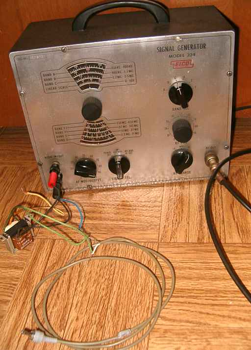
(picture above) Eico 324 with cables and matching transformer showing experimental connections. Insulate yours properly.
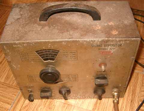
(picture below) rough and dirty Eico 324 as purchased. Hallicrafters collectors will immediately spot the real reason I acquired it. (Yes, that big non-Eico knob.)
Repairs
I already owned another very nice Eico 324 and use it as my general purpose signal generator teamed with a frequency counter for accuracy. I decided to work on this piece to see if even a poor example can be made to perform well. I cleaned it thoroughly with white waterless hand cleaner using old toothrushes, and plastic scouring pads. As usual, I cleaned the controls and switch contacts with contact cleaner. Safety checks showed that the two power-line-to-chassis capacitors were leaky. Those were replaced. I monitored B+ while slowly powering up the unit. Was able to obtain a proper RF carrier at the tuning dial setting with rather decent accuracy, but the audio modulation did not work. I found the two caps on either side of the modulation choke (other side conected to chassis ground) to be quite leaky. Replacing those brought a very satisfactory level of modulation. I then proceeded with tests to determine suitability as broadcaster.
Use as a broadcaster
I fed the audio from the headphone jack of a small solid state receiver with cassette player into the external modulation banana jacks of the Eico. A small matching transformer was used to match the low impedance output of the headphone jack to the high impedance input of the Eico. That transfomer can be a reversed audio output transformer pulled from a typical tube-type radio. One with a turns ratio of about 20 to 1 gives an impedance ratio of about 400 to 1. (The mathematical square of the turns ratio.) The Eico only needs about 3 to 6 volts or so of audio for modulation. It is possible to run the Eico from just the typical low-impedance headphone output without the matching transformer, but a better match and modulation at reasonable playback levels is obtained with the transformer. In a pinch, a small 6 volt filament transformer can also be used, as shown in the picture (yellow center tap wire was not connected). Connect the low impedance side to the headphone jack and the high impedance side to the Eico's AUDIO IN/OUT jacks. Maintain the ground between the headphone jack and the grounded side of the Audio In/Out connectors of the Eico to avoid hum pickup. (In the picture, the blue wire connects both sides of the little transformer to chassis ground and input device ground. ) The level of modulation can be controlled by either the receiver amp's volume control or by the Eico's "AF MOD / OUTPUT" control or both.
For an antenna, I connected 10 feet of insulated but unshielded single wire to the probe or center connector of the Eico's "RF OUT" jack. The signal generator's frequency can be adjusted to a quiet spot on the AM radio broadcast dial. Adjust the volume level of the cassette player's amplifier/ receiver to a level that is sufficient but does not overdrive the Eico to distortion.
Signal strength and coverage
I tested the signal strength using my little Grundig Yacht-Boy 400 because it is not only portable but also has a signal strength indicator. A dial setting at the low-end (530 to 550 KHz.) gave somewhat marginal results. I was only able to broadcast well throughout a display room. However, when tested at 1240 to about 1400 KHz, I was able to broadcast throughout my house with excellent signal strength as well as to the far end of my detached garage, to the deck outside the house, and to a large portion of the yard. Signal strength dropped quickly after about 50 feet with a maximum distance of about 80 feet. I was surprised by the results with such minimal power. I am assuming that the higher frequency was a better match to the 10 foot piece of wire I had draped over the doorframe of my shop. Both this Eico 324 and my other one performed equally well. Your "mileage may vary", but experimentation is fun. Let me know what results you have had.
The manual for the Eico 324 can be found at this link and in several other locations such as BAMA.
The Supreme 570 Signal Generator was the previous item on the bench.