Supreme 570 Signal Generator Supreme Model 570 Signal Generator "deluxe series"
serves as a "broadcaster"
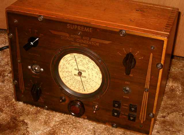
This Supreme model 570 Signal Generator is part of the "deluxe series" as noted on the front panel. It dates from the mid and latter 1930's and has an appealing classic look to it. It fits right at home in a collection of antique radios. The front panel is a wood grain finish on brass plating. The blonde wood case hides a beautiful chrome-finish full shield box which in turn hides a chrome-finish chassis (pictures below). The unit has only two tubes, a 12A7 and a 6A7. These are large 7 pin tubes with grid caps. They predate octal tubes. I am assuming the Supreme 570 was designed, if not built, before 1936, the year of octal-tube introduction. The 12A7 is a combination half-wave rectifier and pentode. The pentode is used as an audio oscillator for modulation. The 6A7 heptode is typically used as oscillator/ mixer in a superheterodyne radio of the mid 1930's, and that is also its function in this set.
Supreme built some well-made test equipment. Here's a link to the Supreme Audolyzer model 562 a complete TRF radio used for tracing signals.
Using the Supreme model 570 as a "broadcaster"
Like certain other signal generators, the Supreme model 570 can be used as a "phono oscillator / broadcaster" to broadcast a signal to nearby AM radios. There has been renewed interest in such a capability for those who collect and restore antique radios. A low-powered "broadcaster" allows the playing of vintage recordings from a cassette or CD to antique radios. The signal is low powered but running a length of wire as an antenna allows pickup of the signal throughout a typical display room. Pease note that the FCC limits antenna length to 10 feet. Power emitted by the generator is well below the limit set for such devices. I have tested several signal generators as broadcasters. Results with an Eico 324 Signal Generator as broadcaster can be found here. The Supreme performed with slightly greater signal strength than the Eico.
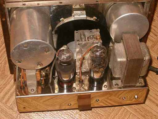
(picture above) Supreme 570 chromed chassis. The flanges for bolting on the chrome full-shield box and the brass spring-clips can be seen in the picture.
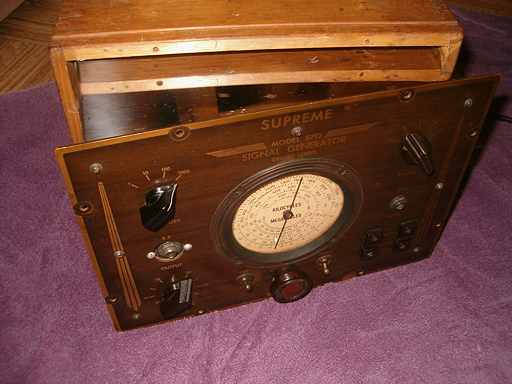
(picture below) Supreme 570 with chrome shield box re-attached. Note the mirror finish reflecting the inside of the wood case.
Repairs
As usual, I cleaned the controls and switch contacts with contact cleaner. Safety checks revealed that the power line to chassis capacitors were leaky. Those were replaced. The power cord is a special shielded type. It was in good condition except for the plug end. I removed several inches of cord and repaired the connections, adding a bit of non-original heat shrink tubing to eliminate any possibility of the power cord shield coming near the plug terminals. On powering the unit, I found that the power supply choke was open. I replaced it with a choke from the "junque" box that matched the mounting bolt holes. The original electrolytic was no longer filtering as evidenced by the hum modulation heard when the unit was powered after replacing the choke. A couple of fresh small electrolytics solved the problem. The internal modulation also did not work. Replacing the leaky 0.02 MF cap tied between chassis ground and the screen and suppressor grids of the pentode solved that problem.
Schematic needed.
I do not have a schematic for this unit. Let me know if you have one that you can copy or scan. The external modulation phone jack labeled "EXT MOD" appears to have some DC on it, but that appeared to be normal according to the original wiring of the set. I would like to see the actual schematic before modifying or placing a capacitor in series with that jack.
Use as a broadcaster
Instead of using the "EXT MOD" phone jack, I used the "freq. mod input" pin jacks on the bottom right for audio input. Those pin jacks lead to chassis ground (appropriately marked GND) and to a capacitor which in turn leads to the screen grid(s) of the 6A7.
Hooking up the "broadcaster"
I used the speaker leads from an external cassette player /amp to feed a spare tube-type output transformer which was connected in reverse to the input pin jacks on the Supreme 570. The level of modulation can be controlled by the amp's volume control. The typical output transformer provides about a 40 to 1 turns ratio so that the speaker output can have sufficient drive to feed the high impedance input on the signal generator. One side of the output transformer's primary and its secondary should be connected together to maintain a common ground connection for both the generator and the audio amp and therefore avoid hum pickup. For an antenna, I used a phone plug with an insulated but unshielded single wire plugged into the "RF Output" jack. The signal generator's frequency was adjusted to a quiet spot on the AM radio broadcast dial. After adjusting the volume level of the cassette player's amplifier to a level that was sufficient but did not overdrive the generator to distortion, I was quite pleased with the quality of the sound from nearby AM radios. I found I could easily broadcast throughout the display room.
I found I could also feed the signal generator's EXT MOD phone jack as I had originally intended with exactly the same results. However, finding some DC on this jack that appeared to be normal for the circuit made me think twice about using that jack when the "freq. mod input" pin jacks worked well without the possible hazard. A simple modification with a 0.1 MF cap in series to that somewhat hot phone jack should solve any problems, but I will not modify it until I can locate and review a schematic for the device.
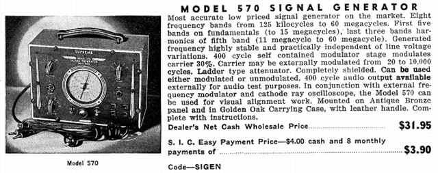
As can be seen in the ad for the 570, the original had a leather handle. The leather handle from this example was removed long ago by a former owner so that the unit would fit more easily on the bench. Here is link to a British owner of a Supreme 570 with the leather handle intact but with the brass spring-clips missing and some rough modifications under the chassis. The full-chrome shield also appears to be missing.
A HomeBrew Transmitter for the 6 meter ham band was the previous item on the bench.