Gonset Communicator IV manual picture
Gonset Communicator IV manual picture
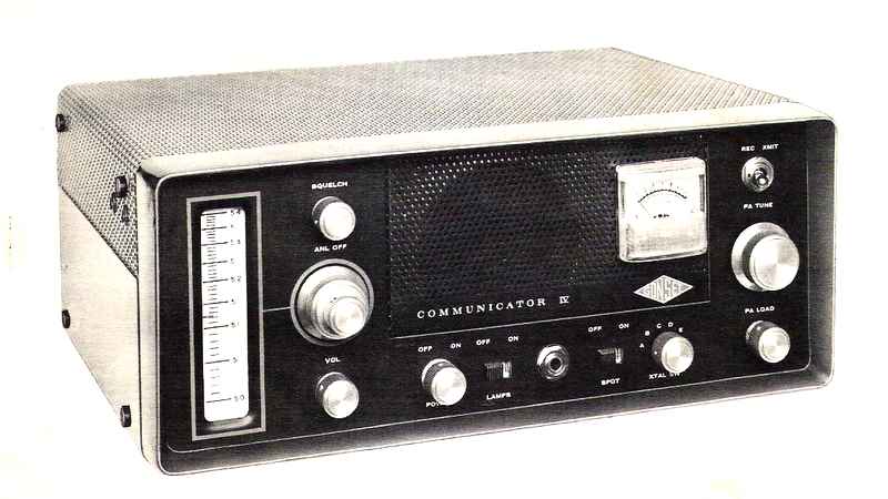
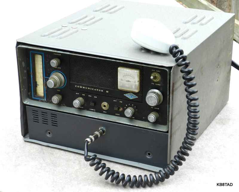
The Communicator IV is the fourth generation of the Communicator series and the first with a low profile. The first version, introduced in 1952, had provision for only one crystal and was designed for the 2 meter band. The very similar Communicator II was introduced a bit later and was known as the "Gooney Box" because of its shape. My 6 meter Communicator II can be viewed at this link. The Communicator III had a similar shape to the II but uses a meter in place of a tuning eye tube. The Communicators were designed primarily for the greater demands of the 2 meter ham band. The 6 meter models were minimally modified versions of the basic 2 meter designs. All of the Communicator models were also sold for Civil Defense purposes. CD models had special CD labels, some painted in bright yellow. In addition to the 2 and 6 meter ham and CD versions, Communicators were also made for commercial AM VHF frequencies and for the aircraft VHF band which to this day continues to use VHF AM to avoid the capture effect of FM. A Communicator IV version was also made for the 1.25 meter ham band.
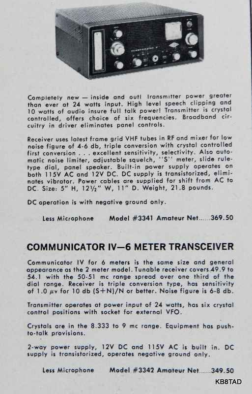
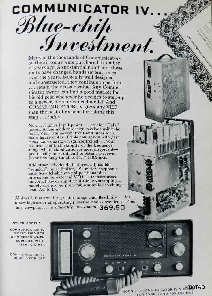
The Communicator IV, allows for switch selection from among six crystals. It uses a pair of power transistors and a separate winding on the power transformer to provide high voltage when operated from a 12 volt battery. It was priced at $349.50 in the 1962 ARRL Handbook. The price jumped to $389.50 in the 1963 Radio Shack catalog. The 1963 ARRL Handbook shows the price at $409.50. The microphone was an extra-cost item.
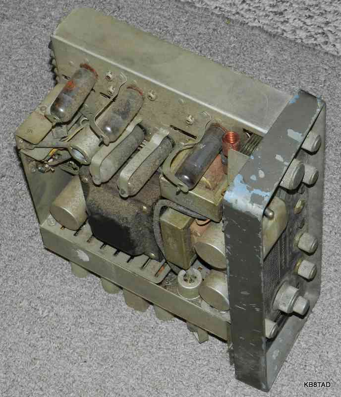
As found - a naked Gonset
I saw this Gonset 4 chassis sitting on the ground at a hamfest. Price tag said $5. I asked about a case or power cord. The seller said no case or cord, but that I could have it for $3. At that price I could not refuse even as a parts set. I probably rescued it from a worse fate if it had remained unsold at the end of the hamfest.
Repair progress
Given its low price, I assumed it might have undergone a major catastrophe such as a dead power transformer. I cleaned it to some extent. With a power cord clipped on to the Gonset's Jones power connector and a clip lead for the jumper for AC input, I checked continuity for AC and found none. Was it the power transformer? A quick test inside the shielded power supply compartment revealed an open power switch.
Using another clip lead to jumper the power switch, I was able to power the set for slow reforming of the electrolytic. After the reforming and at proper power, there was no sound from the receiver, not even a white noise hiss. One of the 6BQ5 tubes had suffered a cracked top nipple. Since the filaments of the two 6BQ5 tubes are in series, a bad filament in one means no glow from either tube. Replacing the bad tube brought a pleasing level of the rush sound of AM VHF white noise. The receiver was working. The set showed promise.
I cut the female end off a shielded computer power cord and soldered a new-old-stock 15 pin Jones female socket onto it for a proper three wire grounded power cord. The safety ground was attached to the center-most opening on the Jones to mate with the ground blade on the chassis power connector.
The non-working on-off switch was mostly sealed. I put the chassis face down on a piece of carpet so that the back of the switch was pointed upward. I then put several drops of deoxit on the rivets and the phenolic insulator. Gravity helped get the deoxit down into the switch by way of the very small rivet openings for a successful switch repair.
I noticed a lack of good continuity at the Jones chassis connector that was apparently caused by oxidation on the blades. They needed more than just deoxit. I scraped the blades clean and then re-applied a bit of deoxit to assure good continuity.
The transmitter portion was physically damaged. The input coil to the 6360 final RF output tube was bent. The bend had also broken the insert for pin 3 of the socket for the 6360. I pulled the 6360. The top piece of the socket insert for pin 3 came up with the tube. I debated replacing the tube socket but decided to locate a donor socket, break it and remove one of the inserts. I was able to push that insert into the now vacant pin 3 hole of the 6360 socket. Final tamping with a small philips screwdriver forced the insert firmly into the tube socket. Straightening and resoldering the coil for the 6360 completed the repair.
An old oscilloscope case happened to fit the width of the Gonset. With plenty of ventilation vents and room, I decided to mount the Gonset in the large case.
The Gonset IV uses a for relay push-to-talk. The microphone plug is a thin 3/16 inch version of a three-conductor stereo phone plug. Not having the proper skinny phone plug and not wanting to change the plug on my existing Turner mike, I opted to simply parallel a standard three-conductor stereo phone jack to the existing mike jack and mount it below the Gonset in the large case.
Original cabinet needed
If you have a junk Communicator IV with a usable cabinet, let me know. With a proper cabinet, I can complete the set.
In the meantime, I will just use the set with the scope cabinet. Output to a dummy load with the original 6360 is 12 watts, just about right for checking into the local 6 meter net. I did that and received good reports on my signal. The audio was "crisp and with plenty of punch" and no hum. I noticed that the receive was very good even on normally weak signals. The squelch/ noise limiter worked quite well on cutting off pulse noise. I did notice some distortion on transmissions from a close neighbor with a strong signal but the AGC was able to manage the signal without my needing to turn down the volume as has been the case with some other rigs. I noticed that the transmit side of the chassis (the right side) puts out a fair amount of heat. I will add a small computer fan to cool the power tubes.
Manual and schematic
BAMA has a schematic for the 2 meter version of the Gonset IV but not the 6 meter version. I originally used the 2 meter schematic since it is mostly identical. The 6 meter set has one less tripler and some other differences. A local ham, John N8XWO, who is net control for the local 6 meter net, has a Communicator 4 with an original manual. I scanned N8XWO's manual. The 6 meter Gonset 4 model 3342 schematics are here. Since BAMA is no longer accepting additional manuals, I will make the scans of the other pages available if you need them. Send an e-mail to my address on the home page. The manual copies may only be distributed for free.
A Heathkit SW-717 Shortwave receiver was the previous item on the bench.