Yes, I know this is not my typical "boatanchor" radio repair. However, I needed a regulated power supply for testing solid-state radio transceivers. Power requirements would be 13.5 volt at 22 amperes when transmitting and less current when receiving. For other needs, the supply needed to be variable from about 5 to 15 volts with voltage monitoring using a meter. Commercial units matching what I needed were in the price range of $150 or more. My goal for the supply was a linear circuit to avoid radio noise (radio frequency interference). I also wanted the supply to be built from totally used and recycled parts, as close to 100% if possible.
Components used:
Older UPS (uninterruptible power supplies) for computer use are considered "throw-away" devices especially after the battery fails or a circuit problem occurs. Many of these older units contain heavy duty transformers which ordinarily are used to boost a rechargeable battery at low voltage to 120 volts AC using solid state switching circuitry. If that circuitry fails, the transformer by itself can be easily re-purposed to produce low voltage AC as a starting point for a high current low voltage DC power supply.
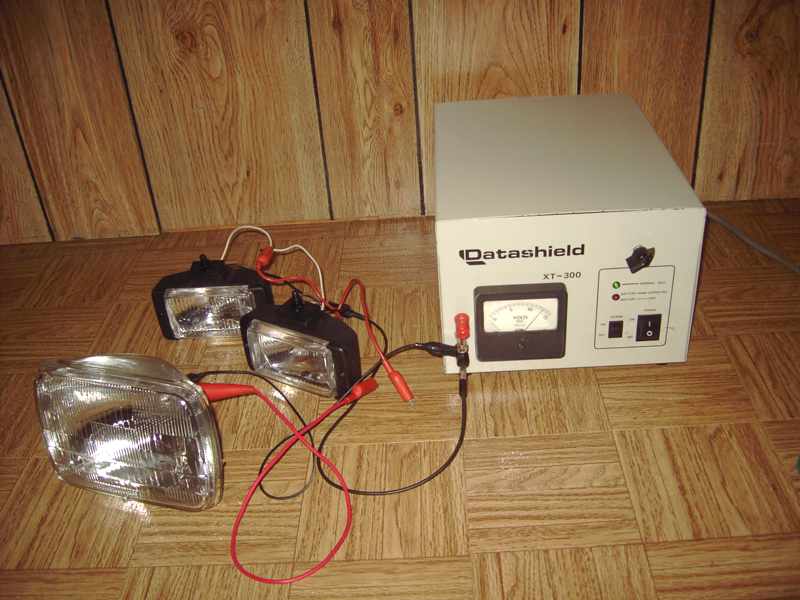
The case, power cord, power switch, pilot light, transformer and fuse assembly were re-used from a defunct UPS, in this case a Datashield XT-300.
A large aluminum heat sink and four high current NPN pass transistors were recycled from a couple of dead audio amplifiers. Four large electrolytic capacitors were also recycled from those amps. The meter, potentiometer control, knob and terminal connectors were sourced from my well-stocked "boxe de junque".
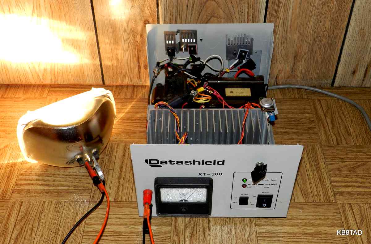
Four dual-diode high power Schottky rectifiers along with their heat sinks, several small capacitors, and a 5 volt three-terminal regulator were recycled from dead computer power supplies. Lengths of recycled twisted pair CAT-5 wiring were used to construct the four very low ohms balancing resistors for the NPN pass transistors.
The only new parts for the power supply were some heat-shrink tubing and some plastic zip ties.
Load testing and a modification
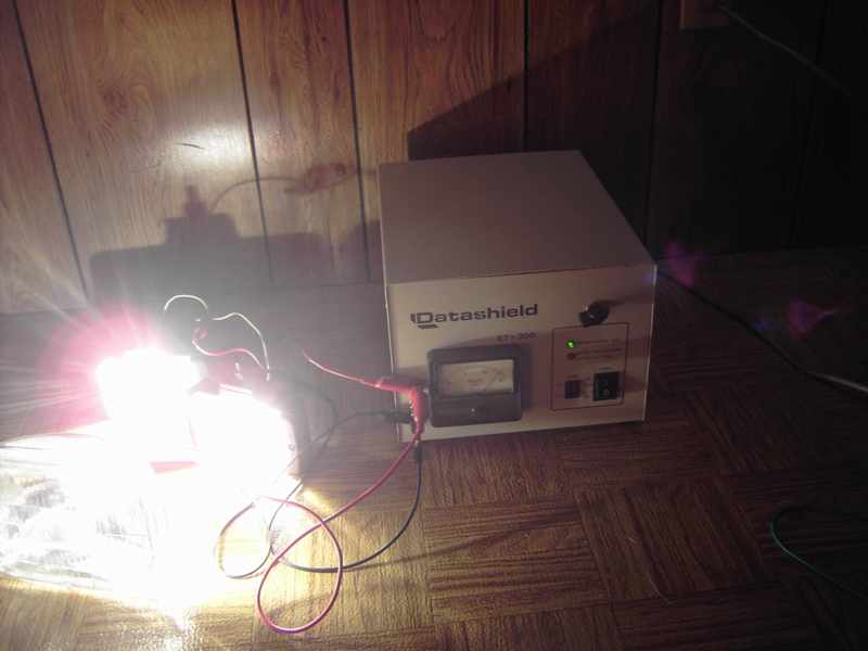
After testing, the power supply did not have quite enough voltage range at full current. I added another transformer recycled from a vibrator supply for a junk low VHF tube type mobile transmitter. When connected to 120 volts input, the transformer supplied about 3 volts output at plenty of current. I wired its output in series-aiding with the output of the UPS power transformer. The extra 3 volts was enough to bring the supply to full voltage when drawing maximum current. A final load with three sealed car headlights, two of which had both the low and high beams lit measured at 23 amperes. (The 3rd head light had its low beam burned out.) At that load, the diodes did get warm but little else.
The workings of a linear power supply:
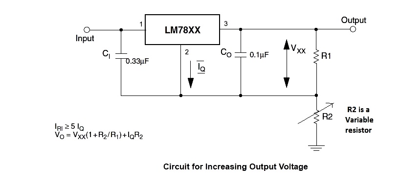
The recycled transformers supply high current AC at low voltage. That AC is rectified through a full-wave bridge using the four Schottky rectifiers and filtered by the electrolytic capacitor bank. The filtered but unregulated DC is fed to four high current NPN pass transistors on a large heatsink. The base current of those transistors is controlled by a three terminal 5 volt regulator which is made variable by a fixed resistor and a variable resistor. The setting of the variable resistor determines the regulated voltage output from 4.4 to 15 volts. Dynamic regulation at full current and 13.5 volts is aided by the impedance of the transformers which at full current produce just enough voltage so that the pass transistors see a reasonable load. Small capacitors to reduce noise and a reverse protection diode were added to the three terminal regulator and control circuit. The 0.6 voltage drop of the pass transistors reduces the minimum voltage of the supply to 4.4 volts. I could also have used an LM-317 for even further reduction in minimal voltage, but I had plenty of three-terminal 5 volt regulators in TO-3 cases and my goal was mainly a 12 to 14 volt supply at full current.
The pass transistors, high power transformers, large filter capacitance, equalizing resistors and heavy-duty diode bridge mimic the circuit used in the typical amateur radio high current supplies with the exception of using the simple 7805 regulator and voltage control. A Google search for the datasheets for the part numbers of the recycled NPN pass transistors and rectifiers let me know the complete capabilities and limits of those components.
Schematic
Here is a schematic of just the simple variable 7805.
Additions
I re-used the green LED as a power-on indicator. The original UPS also had a heavy duty 12 volt relay that I have left in place
for a possible over-voltage cut-off circuit, such as the one in this link .(but the push-button switch would be normally-closed! or I suppose, it could be switched in and out as necessary for protection of the variable supply only when called for, re-using the small "alarm" on-off switch on the UPS front panel with the red LED as indicator.)
A large reverse bias diode was also added for protection of the transistors in the event of a reverse surge such as might occur if the supply was suddenly shut off and was feeding a large capacitor or battery. I plan to add a forward bias diode and current limiter as a separate output for a battery charging circuit. A small capacitor is connected between the positive post and the chassis. The wires serving as equalizing resistors for the transistors are wrapped through an RFI reducing ferrite toroid recycled from a computer supply.
There are three binding posts on the output. The center bright metal post connects only to the chassis. This allows strapping of either the negative or the positive to the chassis or neither. Normally the black negative would be strapped to the chassis.
date: 11-6-14
An HH Scott 340 "Stereomaster" tuner-amplifier was the previous item "on the bench".