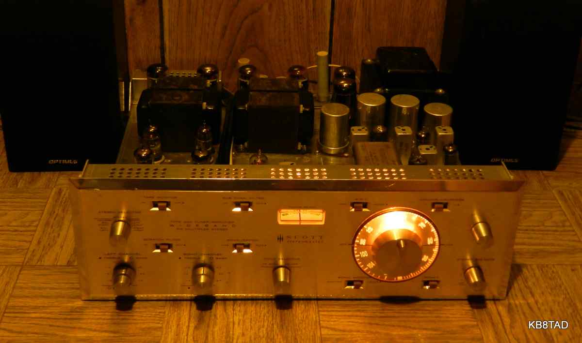
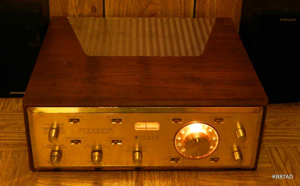
Scott 340 "Stereomaster" tuner-amplifier without its walnut case
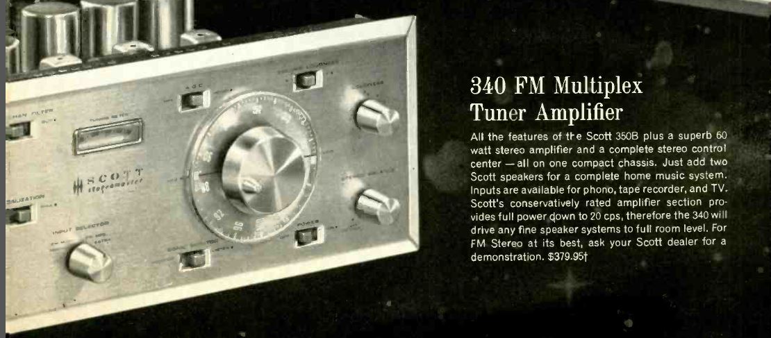
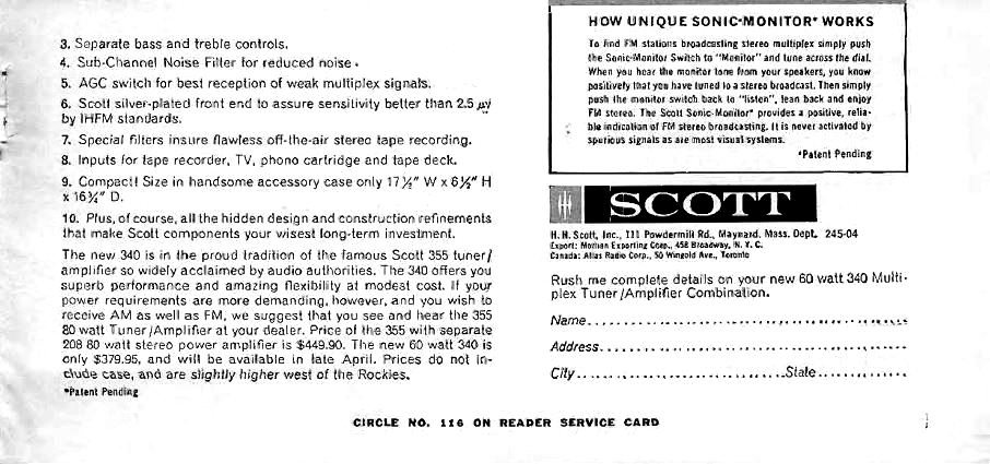
Introduced in April 1962, the HH Scott 340 "Stereomaster" tuner-amplifier is rated at 27 watts per channel for a total of 54 watts RMS (advertised at 60 watts output and later 70 watts). The set essentially combines the Scott 350 FM multiplex tuner with the Scott 299C amplifier. It has a total of 20 tubes including four 7591A output tubes and a pair of 5AR4/GZ-34 rectifiers. Advertised price for the 340 was $379.95. The optional case was an additional cost. The set is now often identified as a Scott 340A to distinguish it from the very different 340B.
Repairs
Except for an accumulation of dust and dirt, the set was in good cosmetic condition including the wooden case. Dirt is typical for a set that has not been used in a long time. I gave it a thorough cleaning with waterless hand cleaner and old toothbrushes and rags.
After safety checks such as checking the fuse for proper size and for any line to chassis leakage which was not a problem in this set, I often do an initial power-up without the high voltage rectifier tubes to check the AC voltages from the power transformer and proper current draw for just the filaments. That is an important step in this set and many other high power audio tube sets using a fixed bias supply as opposed to cathode bias. The cathodes for all the 7591A output tubes are directly grounded. Proper negative grid bias voltage is vital in such sets.
The bias supply
The bias supply in the Scott 340, like similar sets, is by way of a small full wave selenium bridge rectifier. I checked its output voltage. The manual and schematic do not show the voltage output from that bias rectifier, but it supplies the DC filament voltage for four 12AX7 series-connected preamp tubes. That means the supply must deliver about 48 volts output after the filter capacitors and resistors. It wasn't producing even half that which was obvious because the four 12AX7 tubes did not show a proper filament glow. That result was not surprising. I replaced the little selenium bridge with a silicon bridge expecting to have to reduce its output to match the 48 volts. However, the voltage from the bias supply with the silicon rectifier in place was spot-on.
I did not immediately check the balance pots for the grid bias adjustments on the output tubes, a mistake on my part. I had checked resistance on those pots and had not found a problem.
On checking the output tubes and rectifiers with my stingy TV-7 military tube tester, I found one pair of 7591A tubes to be weak, but the other pair and the rectifiers easily passed the test. I decided to just test one channel of the amp section at a time, using the weaker tube pair. I connected an antenna clip lead and a test speaker to the one channel and set the controls to FM stereo. Then, watching the AC ammeter closely, I slowly powered the set. After the 5AR4 pair kicked in, I heard the pleasing sound of FM off-station rush noise. It was working, but the ammeter was slowly inching towards about 1.8 amps, too much power draw with only one channel active! I shut off power. Time to check under the hood (with the tuner-amp on its back). I quickly isolated the cause, zero grid bias. Not the best thing for 7591A tubes which, at the voltages in this set, are running near their margin. However, I had new respect for this "weak" pair of tubes.
The problem turned out to be the balancing pot on the channel I was testing. While measuring fine end to end, the tap was not making proper contact. These are nominally 100K ohm linear pots. I pulled the offending pot and opened it. The sliding contacts were being interfered with by a greasy substance that I assume was hardened lubricant. There was no physical damage. Cleaning the inside and applying some more DeOxit directly saved the pot. I made sure the other pot which was intact was also cleaned.
The now functional pot resulted in the proper bias on the tubes, about -22 to -23 volts which was correct for the applied levels of plate and screen voltages according to my tube manual. I also re-balanced the pots so the movable contact was at its electrical center. On testing again the set drew proper current. I then inserted the second pair of 7591A tubes and connected test speakers to both channels. The current draw settled at 1.50 amps at 117 volts and 1.55 at 120 volts AC. With a full-quieting local station tuned in, that current draw would pulse upwards somewhat with the volume cranked up on loud bass music passages. That was as expected for class AB1, again according to the tube manual.
"Scratchy" tuner
The FM tuner was working but scratchy as I turned the dial. The stations would jump in and out erratically as I tuned. I had seen this problem before in other tuners. Removing the variable cap shield cover, I applied DeOxit to the grounding points and bearings on the cap. That cured the problem. I was now able to tune some very weak stations easily.
Listening to stereo or monaural at both low and high volume, I could not tell which pair of output tubes was doing what. The "weak" pair of output tubes was as capable as the pair that tested as new.
Cracks in the tuning dial
The tuning dial was loose. I pulled the metal knob and could see where the clear plastic tuning dial had cracked from a too-tight set screw adjustment. The crack was only visible with the knob removed. I applied cyanoacrylate glue to the crack and later wrapped a couple of turns of bare hook up wire around the tuning dial shaft hub, tightening those turns and then soldering and trimming the twisted ends. That reinforced the plastic dial substantially allowing adquate tightening of the set screw.
Listening to it
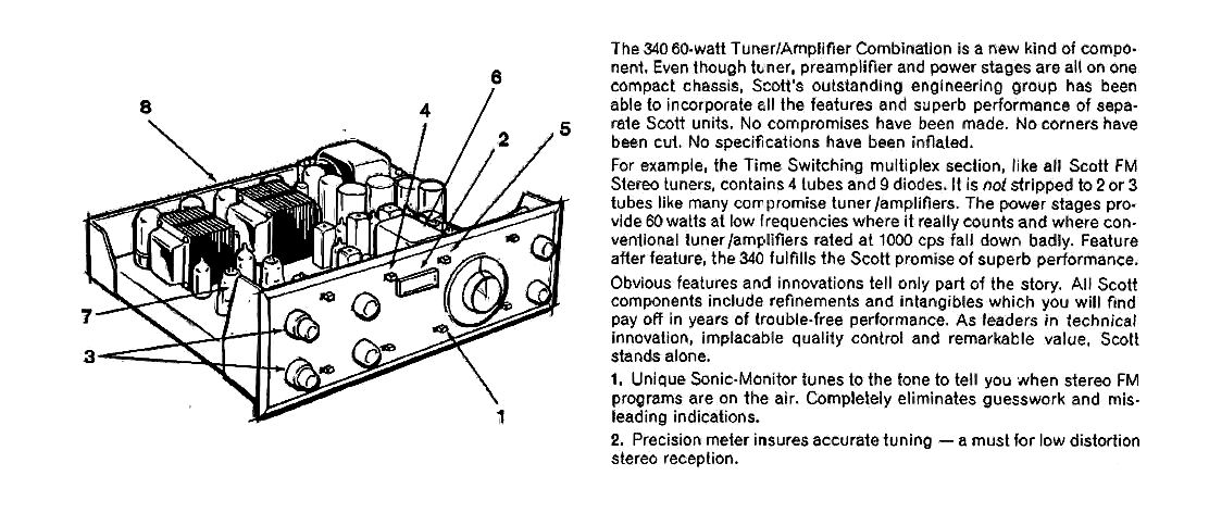
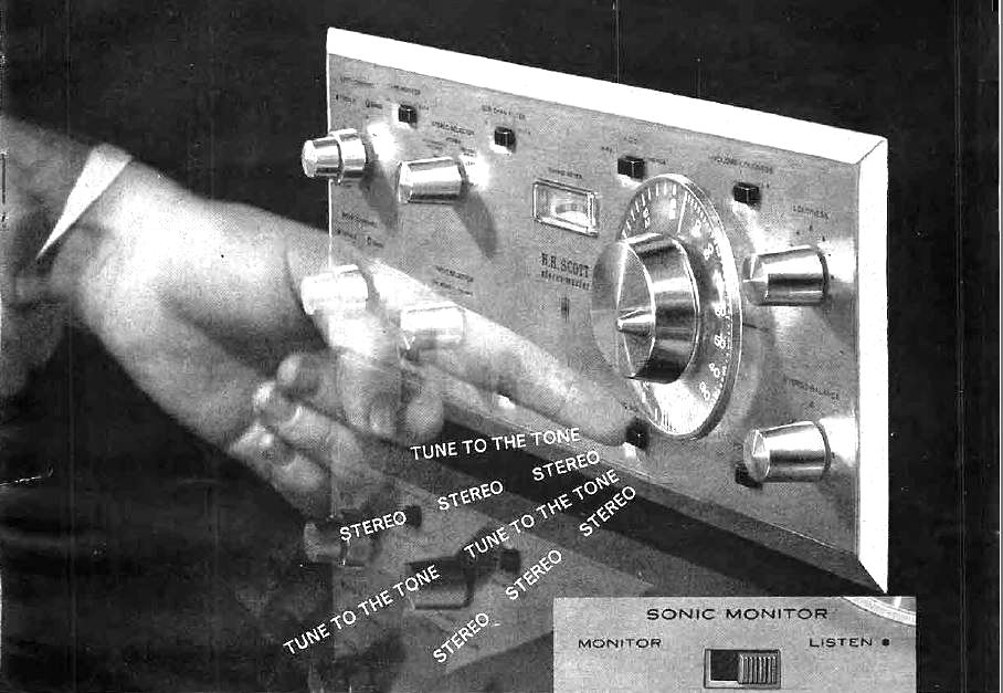
I spent the next hour or so listening to the set on a weak oldies station, marveling at the FM sensitivity and audio performance. The "Sonic Monitor" could be switched in to locate stereo stations. It causes a tone to be heard over the speakers whenever a stereo station is tuned in. Stereo stations were not the norm in 1962, but monaural stations are the exception today.
Manual sources
A manual with schematic for the Scott 340 can be found at this link.
Here is a
link to the schematic from the vintage independent HH Scott website.
More audio equipment
I have repaired a number of other pieces of audio equipment.
A list and links to those devices can be found here.
date 10-7-14
A Fisher KM-60 FM tuner "StrataKit" was the previous item "on the bench".