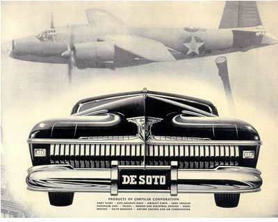
Chrysler Corporation ad in 1942
from Car production to War production
1942 Motorola Car Radio ad

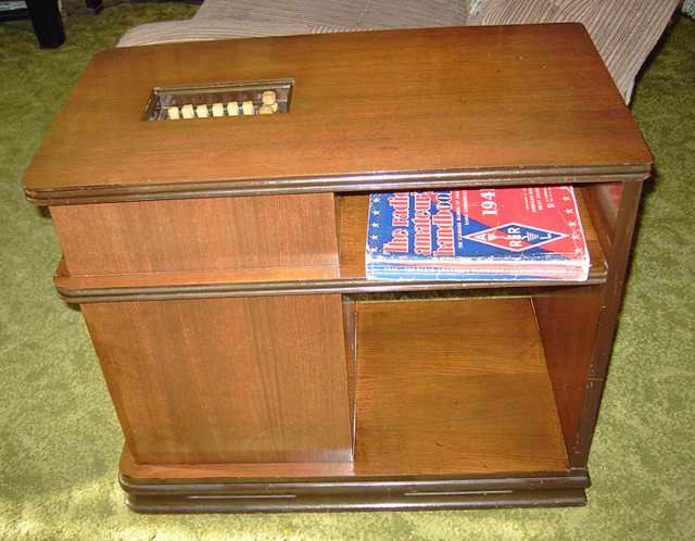
The "Car-Side" Chairside radio resulted from World War II
In addition to tube-type communication gear, I occasionally enjoy working on antique entertainment radios especially if they are interesting or unusual such as this one which represents a slice of history. With the attack on Pearl Harbor on December 7, 1941, the US entry into World War II affected all civilian manufacturing. Automobile production ceased in February 1942 as did radio production for the home. Automobile radios were optional equipment in new cars (as was the heater!) What to do with all the car radios prepared for the 1942 model cars? Especially since home radios were no longer produced?
Showing up in stores in Summer of 1942 were some of the 125,000 automobile radios Motorola converted to 115 VAC according to Ted Lind's time-line for Motorola's CP Division. Some of them showed up in Chairside cabinets such as this one. Obviously, wood for furniture-making was not on the restricted list. The model number of the Motorola will be 47D1 or 47D2. Model 47D2 was installed in the chairside. It has 6 tubes and single ended audio. I have also repaired an 8 tube Motorola model 47D1 which has push-pull audio output and a few other variations but the same external shape. Schematics for both of these automobile radios can be found in Rider's volume 15, Motorola pages 33-36. The elongated radio shape of these two models was designed for installation in the 1942 Chrysler Corporation cars including Chrysler, Dodge, Plymouth and DeSoto. It was this elongated chassis shape of the Chrysler radios that was likely to find its way into Chairside cabinets.
Motorola Chairside was purchased by my wife at a radio swap meet.
Front of Motorola Chairside showing slots cut for the speaker grill.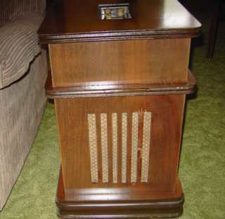
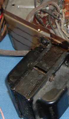
"What's inside". The Motorola Chairside chassis 47D2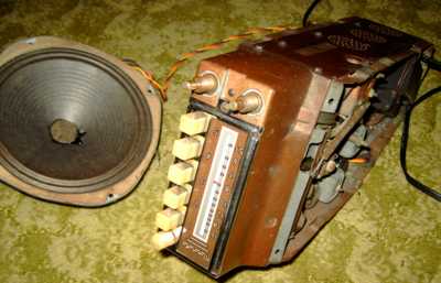
An auto radio conversion actually makes for a sensitive AM broadcast set. Many older car radios, including these 1942 models, had a tuned RF amplifier stage with a front end that matched a short antenna. The sets were designed for very good sensitivity in a relatively noisy automobile environment.
Philco also made radios designed for the Chrysler cars with the same elongated Chrysler form factor. Like Motorola, Philco also converted their long Chrysler car radios into chairside sets. A picture of the Philco chairside conversion, model A-801, can be viewed at this Radio Attic link. The Philco version of the chairside furniture piece is quite a bit larger and has its knobs protruding above the top surface. The Motorola Chairside is much more compact and the knobs are recessed. Slots for air circulation were designed into the base trim and the back of the radio compartment next to the magazine rack section.
Conversion to 115 AC power
A replacement transformer was typically shoe-horned into the Motorola set to replace the vibrator power supply. While the one in this set fits the space left after removal of the vibrator and original transformer, the replacement transformer is held in place by heavy wire, not by bolts. The result is very secure mounting but definitely makes the conversion look like the afterthought that it was. An 8 inch electrodynamic speaker was added with the field coil doing double duty as power supply choke. The conversion power transformer likely had too high a B+ output, requiring the rather large dropping resistor that I had to replace. For antenna, this set has a heavy enameled copper wire attached via insulated staples to the bottom periphery of the set. That wire ends in a Fahnestock clip which also connects to a wire leading to the car radio's antenna jack. The antenna and ground are bridged by an added 1000 ohm resistor, probably to protect against static discharge.
Lots of repairs
The power cord had been cut off long ago. I replaced it and the flaking rubber-covered wires to the electrodynamic speaker. One of the old caps had shorted and been the cause of the radio's demise. It was one of two 0.1 MFD screen bypass caps. I located the short because I always check for resistance from B+ feeders to ground before power up. Finding one of the B+ leads with low resistance led to a search for the cause. Not surprisingly, that led to a shorted cap. I ended up replacing nearly all of the dry caps as well as the electrolytics. I also replaced the sand-style power dropping resistor, installed as part of the conversion, because it was intermittent. The set started playing when I powered it up slowly via my isolated variac to half its normal voltage. It played for a few minutes and then quit while the ammeter on the variac pegged. I cut power quickly. I suspected the 6X5 rectifier had developed a short. A quick check with the tube tester confirmed that suspicion. I strongly recommend adding a properly-wired fuse to an old set. This is especially important when the set uses a 6X5 with its possibility of heater to cathode breakdown. I replaced the 6X5.
After playing the radio a bit more while watching voltages carefully, I thought I smelled just a bit of that very distinctive odor of arcing and failing carbonized insulation. The output transformer quit shortly afterwards, open primary. The output tube needed a 3000 ohm primary according to the GE tube manual. With the typical 3.2 ohm speaker, that meant roughly a 930 to 1 impedance match. A transformer of 30.6 to 1 turns ratio will give a proper impedance match. Turns ratio is of course directly related to voltage ratios. I managed to find a replacement in the "boxe de junque".
I had to grind a bit off the inside edge of the face casting, believed to be of zinc, since it had warped a bit and was interfering with the free movement of the tuning cap on the upper end of the dial.
Fun with the dial cord
There are two dial cords in this radio. The thin dial cord that actuates the pointer on the tuning dial was broken. Replacing it requires removal of the face casting to get at the tuning dial pointer and pulleys. The dial cord restringing will definitely try one's patience since the face casting with the tuning dial has one part of the dial string but the pulley for the tuning cap is on the main chassis. The two have to be separated to restring the dial cord. I used masking tape to hold a very long piece of dial cord in place on the face casting pulley and guides. Then I threaded the main pulley with the face casting still loose and carefully pulled up the slack on the dial cord while carefully bringing the face casting toward the main chassis and positioning it back onto the radio. Definitely not a simple task. For dial cord, I use 65 pound "Spider Wire" fishing line bought at WalMart.
Questions about the conversions
To my knowledge, the Motorola car radios were after-market items sold and installed by dealers. I was left wondering if the Motorola radio conversions had been done at the factory or whether Motorola supplied the furniture pieces to their car radio dealers and had the dealers do the actual conversion and installation. If you have the answer, let me know. Also, please let me know if you have a 1940's advertisement for this set or other information. If you have a similar Motorola Chairside, let's compare notes regarding the transformers and speakers used in the conversions. I'm curious as to whether these were a standard single type or whether they were off-the-shelf replacement stock.
Update, Another Motorola chairside conversion
Jim D. wrote and sent pictures of his 47D1 chassis in a Motorola chairside cabinet. The transformer had been mounted on the outside of the chassis instead of in the space formerly occupied by the vibrator transformer.
A Navy TCS-12 receiver by the Collins Radio Company was the previous item on the bench.