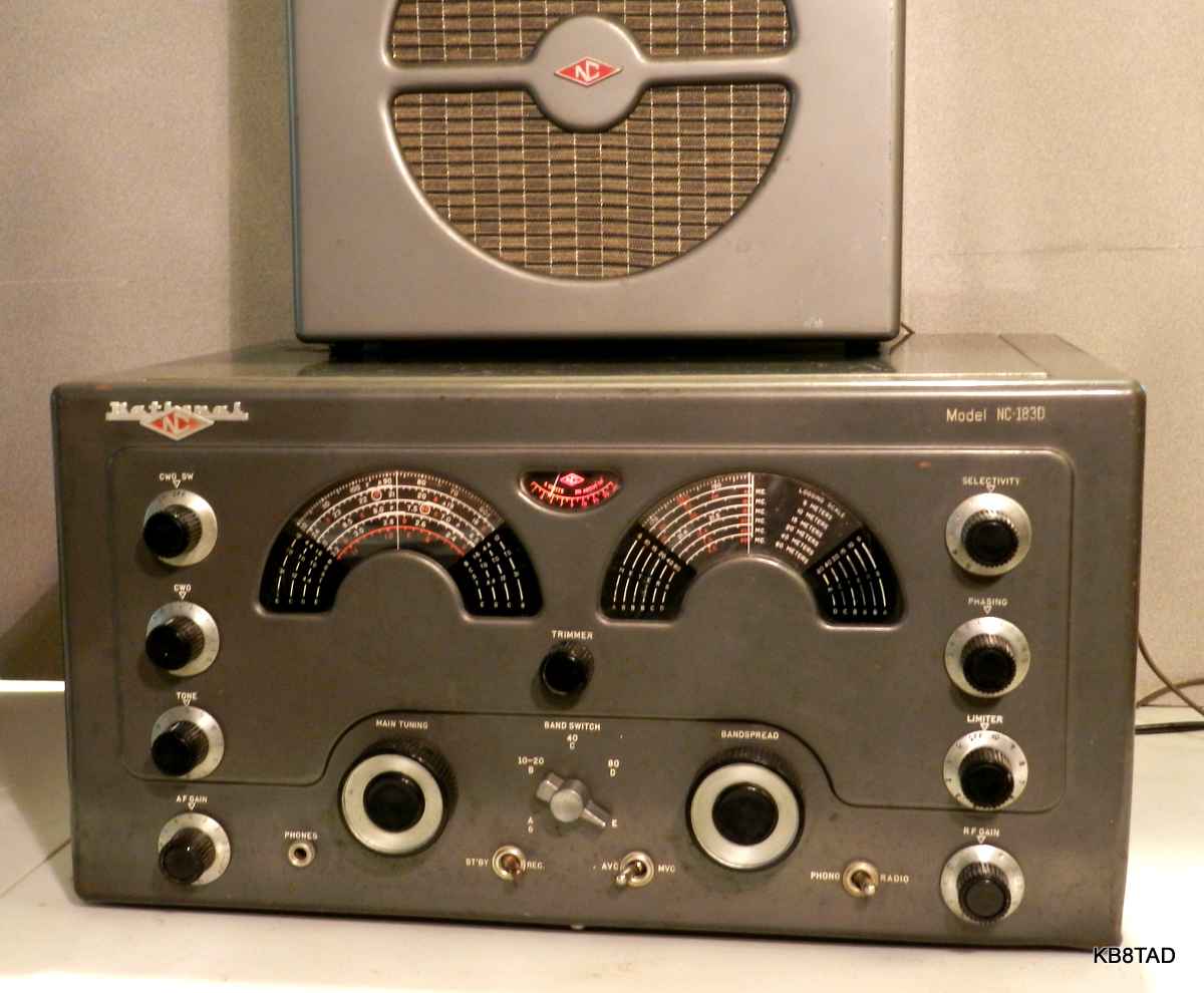
National NC-183D
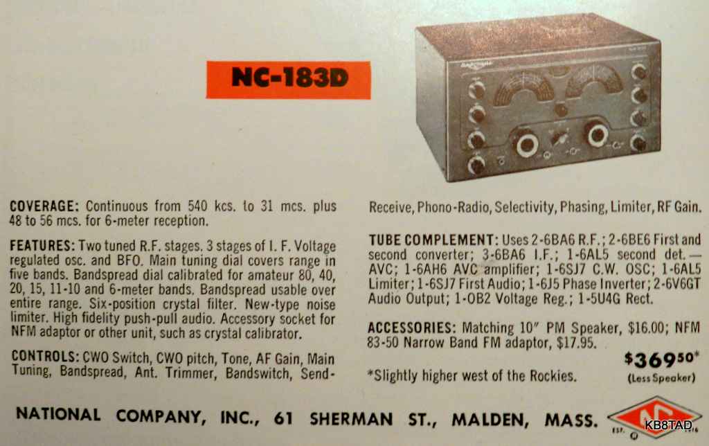
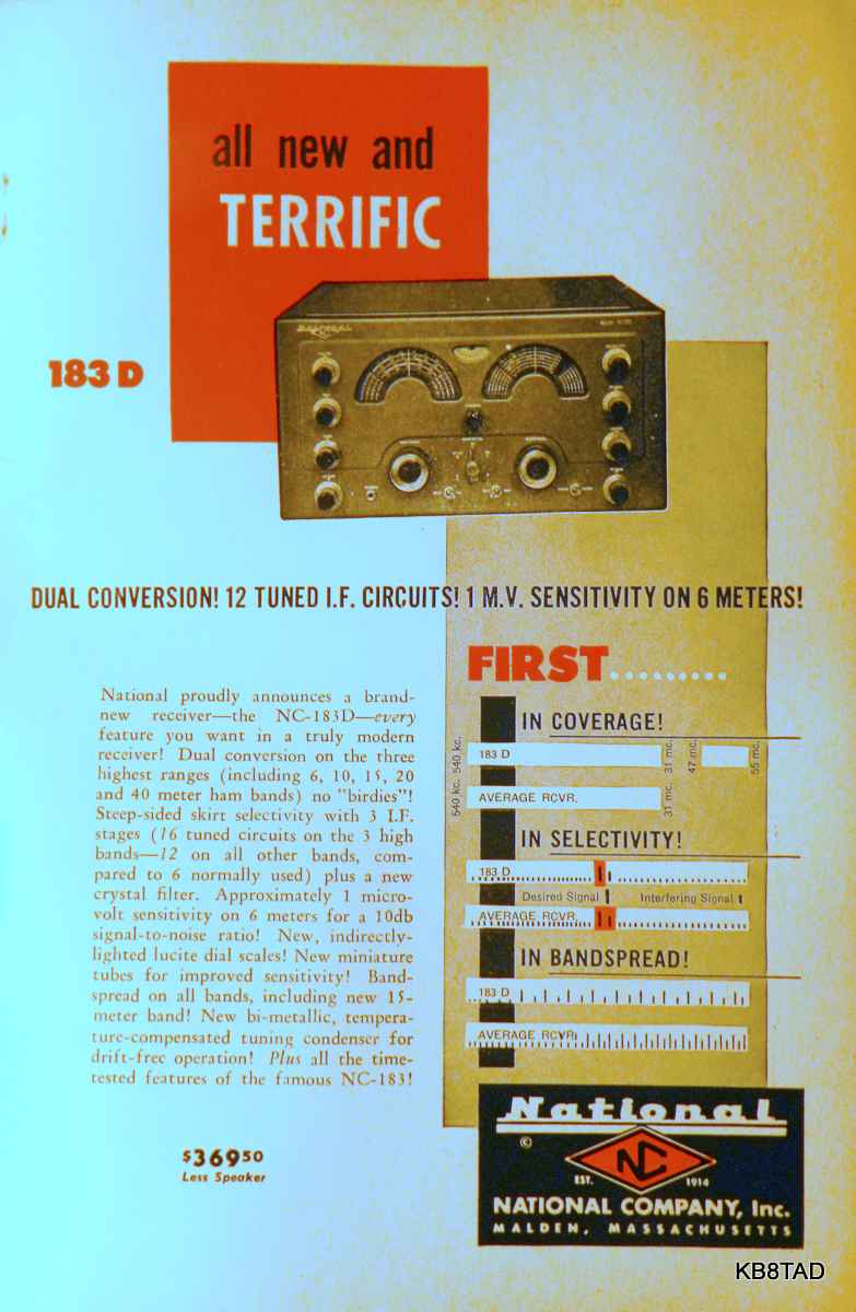
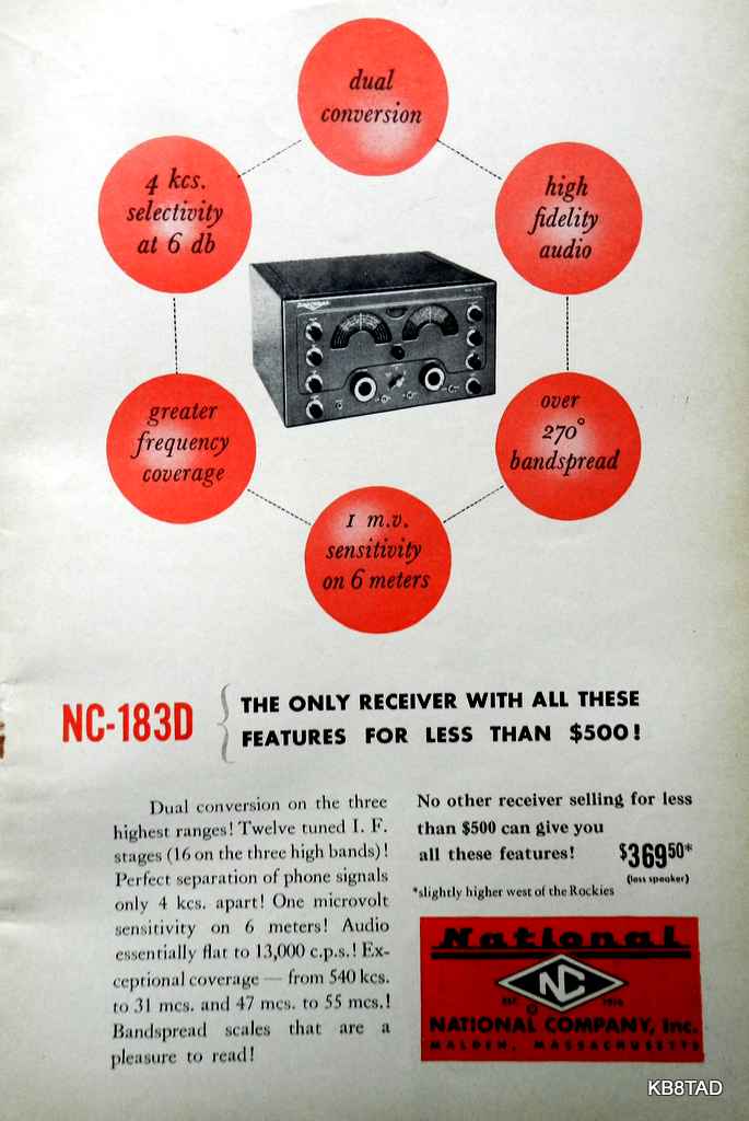
National's NC-183D is a 5 band dual conversion communications receiver covering AM broadcast and shortwave from 540 KHz to 31 MHz plus the 6 meter band from 48 to 56 MHz. IFs are 455 KHz and 1720 KHz with the latter switched in on the upper 3 bands. Price at introduction was $369.50 plus $16 for the 10 inch PM speaker, serious money in 1952, about one fifth the price of a new car.
As purchased, this example used a 6J5 for phase inverter. A later variation used a dual triode 6SN7 for that function with one of the triodes serving as S-meter amplifier.
Waking a dead set
I had read on the net that some of these sets have capacitors from the transformer high voltage windings to ground which if shorted can burn out the power transformer. This set did not have such caps. A proper fuse should prevent such a problem. Most of the caps in this set are ceramic including the critical audio caps to the 6V6GT input grids. Ceramic caps are not prone to leakage.
After unpowered safety checks and inserting a proper fuse, about the only thing the radio could do was amplify audio from the phono input with the sound distorted. The RF and IF stages were dead. I checked tube voltages. All of the 47K ohm resistors in the set had drifted very high, a common problem in this model. Those resistors are used for the screen voltages for the RF and IF stages and the phase inverter balance. I checked all the other resistors and replaced several more. Now at least the screen grid voltages were in the normal range but the set was still nearly dead. I discovered a simple modification that left the first RF tube at full gain, not under AVC or RF gain control. I left it in for the time being.
I next checked the tubes especially the 6BA6 and 6BE6. Both 6BE6 tubes and three of the 6BA6 were nearly flat. Replacing them brought life to the set. The RF gain control was open on one end which maximized the gain. I replaced it with a proper one from the well-stocked "boxe de junque".
In checking the oscillator for the lower two bands, I found both the RF and IF alignment off considerably. Someone had apparently tried to align the set to solve its other problems. After alignment, the set finally came alive with excellent sensitivity on bands D and E, the single conversion bands under 4.4 MHz. In fact those bands were "hot". On 80 meter SSB strong signals, it was almost too hot. I found I needed to turn the RF gain all the way down to limit the sensitivity. This despite the fact that the RF gain at that setting was at its proper full negative voltage. I suspected that removing the first RF tube modification would be necessary.
However, bands B and C, the high frequency dual conversion bands, had sensitivity levels that were functional but at very much lower levels than bands D and E. I checked and re-checked not finding any obvious electronic fault that would explain that. I had aligned the pair of 1720 KHz IF transformers using a scope for peaking. All adjustments had peaked well. Was the 1265 KHz oscillator not injecting enough signal? Sniffing with my frequency counter said otherwise. The 6BE6 pair were new and tested as such. Swapping them made no difference. I doubted that there would be that large a sensitivity difference between the bands although there were reports on the net of such. I puzzled over the situation and schematic with the suspicion that somehow I had to have overlooked a problem in the 2nd conversion stages.
A "eureka" moment
Testing again, I was listening to a weak station at around 18 MHz on band "B", the highest frequency shortwave band, RF and AF gains maxed while checking voltages at the second 6BE6 and its 1265 KHz oscillator / converter stage. I put the prod on the IF transformer side of the 22 ohm resistor feeding the input grid and noticed a slight increase in signal strength. Huh? Why would that happen especially since both sides of the transformer were peaked properly in alignment? As I moved the prod a bit while still touching that point, I could increase the sensitivity a bit more. I was either adding a bit of capacity or my voltage prod was doing regeneration or something.
Long story short, the culprit turned out to be the 5 pF cap between the two 1720 KHz IF transformers. It had passed the tests before when I fed the various points with a sig gen, monitoring via the scope. I suppose a very small 5 pF cap that is open inside can still be a 1 pF or so cap with just its leads in proximity. I replaced it with a new 5 pF silver mica and the two upper bands now had nearly the same sensitivity as the two lower ones. This was one hot receiver, especially since by now I had replaced the 6BE6 pair and all five of the 6BA6 tubes with new mil-spec versions in attempts to improve the sensitivity on the upper shortwave bands.
Fixing the 6 meter band
The 6 meter band initially was dead. I traced that to the oscillator not functioning as seen on my frequency counter. Since the oscillator worked fine on the other bands, the problem was unique to the 6 meter band. That band has coils that obviously have the least amount of wire and the least resistance. Just a little resistance in the circuitry would affect it more than the other bands. The band is also tuned just by the bandspread cap. I noticed that the bandspread cap grounding was by way of wire to several solder lugs to screws to the chassis. Those screws also have to go through an aluminum angle strip before touching the ferrous-metal chassis. I loosened the screws, cleaned them and the mounting strip with deoxit and tightened them again. That solved the problem.
Performance
While tightening the bandspread cap grounding solved the 6 meter oscillator problem, that band was the weakest in RF sensitivity, especially as compared to the typical dedicated 6 meter transceivers of the 1950s and 60s.
However, on all the other bands, the NC-183D with all new RF and IF tubes, proper resistors and operating to specifications is one hot receiver! On the 80 meter ham band it was too hot. I was tuning in SSB conversations with a clip lead for antenna. Using the hamband antenna, I literally turned the RF gain all the way down and still had to detune the antenna peaking to reduce the signal level. At this point, I removed the modification that left the first RF tube at full gain. At the same time, I also replaced all three resistors on the end of the bandswitch. Those set the individual sensitivity levels of the bands with the RF gain maxed. All had drifted upward somewhat. I wanted to make sure that the set still had full sensitivity as intended by National after removing the mod.
With all the work completed, the NC-183D could easily keep up with my solid state Kenwood TS-850S/AT. I could see why this radio was a winner in its day.
Those "B+ hot" terminal screws
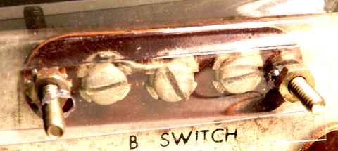
A terminal strip marked "B switch" on the back of the chassis, the same type of terminal strip as the speaker and antenna connections, is for remote control of the standy-receive function. The full B+ voltage is on those terminals at all times, a dangerous "gotcha" for the unwary.
A previous owner had already replaced the terminal strip mounting bolts with longer ones with threads pointed out, probably to act as a bumper. I cut a clear plastic insulator from packaging material to cover that terminal strip using the long threads of those mounting bolts for attaching the plastic.
6BA6 substitute
I was afraid to deplete all my new 6BA6 spares but found out that the 6BH6, of which I had plenty of spares, is a good plug-compatible substitute for both RF stages. The 6BH6 has similar specifications to the 6BA6 but the pins for suppressor and cathode are swapped. With both going to ground as indicated by the schematic, the tubes would be plug compatible. Two of the three IF stages in the NC-183D also have both the cathodes and suppressor grids grounded. I have not yet tried it but those two positions should be plug-compatible as well.
Manual and schematics can be found
on the BAMA site
More National sets
I have repaired and documented other National radios.
A list and links to those National radios can be found here.
Date 7-11-14, 7-14-14
A Hallicrafters S-76 receiver was the previous project "on the bench".