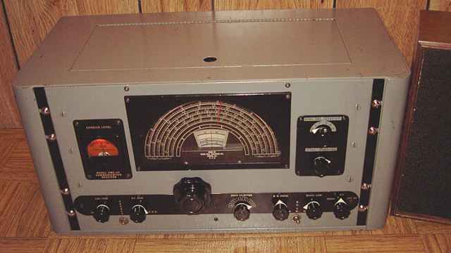

The RME-45B tuning has one of the highest vernier ratios of any boatanchor direct tuning system I have yet encountered other than perhaps the military R-390. Over 80 rotations of the larger tuning knob are required to traverse the tuning dial and over 400 turns of the smaller knob are required. As a result, the tuning dial can be set quite accurately for the frequencies of the lower ham bands.
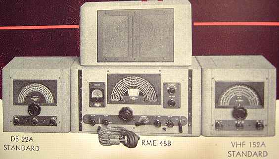
As shown in this picture from the RME ad in the 1948 ARRL Handbook, accessory converters such as the VHF-152A and the DB-22A preselector were offered that matched the height and cosmetics of the RME-45B.
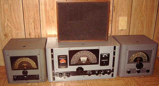
See the matching RME DB-22A preselector , the VHF-152A converter and the HF-10-20 converter.


Repairs
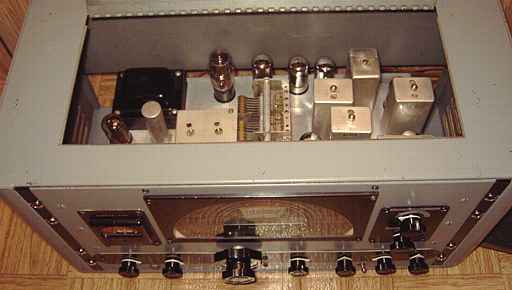
The paper capacitors in this set had been replaced by a former owner. The work appeared to be well done. I replaced the incorrect 5U4 rectifier with the correct 5Y3. The 5Y3 takes only 2 amps of filament power while the 5U4 takes 3. After cleaning, application of deoxit on the controls and sockets, and the usual safety checks, I proceeded with a slow power-up using my isolated variac. The radio played decently but the BFO was not functioning. I did some testing and also tried another 7B6 tube but no change. I finally removed the shield from the BFO coil and found the problem. The primary winding was loosely hanging on its wires. Someone else had tried to repair the BFO earlier. I remounted the coil on the wood dowel separator re-using the bees wax that had cracked in several pieces. Just a bit of heat from the solder gun resealed the primary on the dowel. After repairs, the BFO was working but also injecting occasional popping and frying noises. I then replaced the old BFO mica caps with new dipped micas. After this the BFO behaved normally. I suspect a former owner may have tried to repair the popping and frying noises. Normally the mica caps do not need to be replaced along with the paper caps but in this case, the need was clear.
The knobs for the bandswitch and function switch match the others but are believed to be incorrect. (See the ad photo.) I will look for the lever-style knobs. The bottom plate was missing in this set. I substituted an aluminum plate.
Alignment
My frequency counter and listening to the crystal filter confirmed that the IF was aligned on 455 KHz. I tweaked the alignment for RF, converter, and oscillator settings just a bit. Several of the bands showed a major improvement in sensitivity when the converter settings were tweaked. I was experiencing good sensitivity before the alignment tweaking, but ended up with excellent sensitivity afterward. I adjusted the oscillator just slightly so that the receiver would be almost perfectly accurate on my favorite ham bands. For example, the bandspread for an RME-45B shows the 80 meter ham band to a 3 place accuracy. (such as 3.95 MHz). I was able to set it to track at that level of precision. Listening to 80 meter SSB on this set, with its extreme vernier capability, accurate dial, and properly adjusted BFO, is among the easiest of any receiver of its vintage (all without product detector). The manual states that "the smaller knob turns 62 times in tuning from 3500 to 4000 kc. while the larger knob turns nearly 13 times. The 3.5 Mc band takes up 11 5/8" on the band spread dial."
Cal-O-Matic tuning
is what RME calls their bandspread dial and markings. According to the RME publication Getting the Most Out of Your Receiver, Part II,
Power draw
I checked power draw with the correct 5Y3 versus the 5U4 originally in the set as obtained. As expected the 5U4 took an extra 5 or so watts. The Sams Photofact for the set lists current draw as 1.53 amps at 117 volts. That is very much an ERROR. The RME manual indicates 90 watts at 115 volts, about 0.78 amps. I measured power draw at 115 volts (with the AVC on) and found the power draw to be correct according to the manual. I also noticed that the receiver would operate at a voltage of 105 and lower, with a drop in power consumption, but with no apparent loss of performance and with a proper glow from the voltage regulator tube. I had another 5Y3 in the "boxe de junque" that had been labeled "weak". On a hunch, I substituted the "weak" 5Y3. Sure enough power draw dropped slightly to only about 0.78 at the full 120 volts AC socket power. The B+ was still fine. I left the "weak" 5Y3 in the set so that the normal 120 volts would not cause undue heating of the power transformer.

The RME manual, schematic and alignment instructions can be downloaded from BAMA as well as from Nostalgiaair. It is listed in Rider volume 15 and in Sams Photofacts 473-25. The BAMA site has a handy annotated schematic with component values added.
Performance
I consider the RME-45B a top performer for the immediate post-war era (late 1940's). It is my choice of a suitable amateur receiver match to the Viking I transmitter of the same vintage.
A Zenith 1948 radio-phono console with old and new FM and dual tone arms was the previous item on the bench.