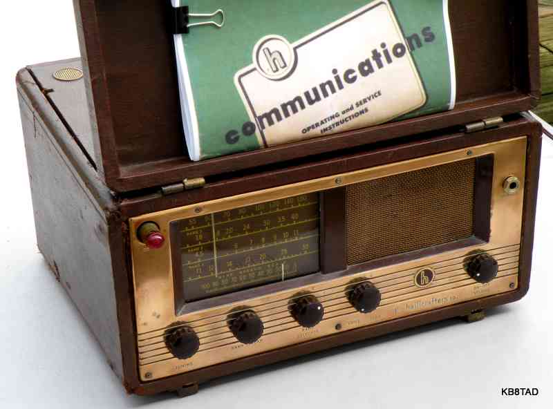
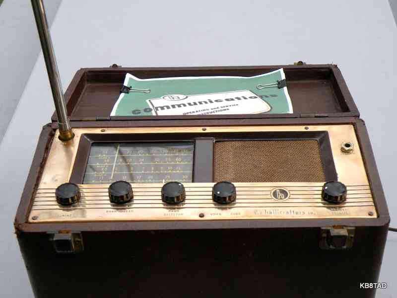
Hallicrafters S-72 portable receiver
The Hallicrafters S-72 is a 3 way suitcase portable receiver with broadcast and 3 shortwave bands fully covering 550 KHz to 30 MHz. It features bandspread and a separate RF gain control that also turns on the BFO.
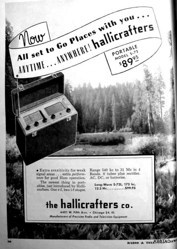
It is quite sensitive with a tuned RF stage and dual amplifier tubes in its IF stage. A loop antenna is used for broadcast and a rod antenna for short wave. The set was produced from 1949 to 1951. The 1949 price of the S-72 was $79.95. In 1950, ads show a price increase to $89.95. In 1951, the price rose to $109.95.
Comparison to the Zenith Transoceanics
Similarities
The Zenith Transoceanic
8G005Y and the similarly-styled G-500
and later the H-500
were the competition for the S-72. Both the S-72 and the Transoceanics were 3 way portables, capable of running on AC, DC or battery. The S-72 uses 7 pin miniature tubes as do the G-500 and the H-500. The suitcase size of the S-72 is similar to that of the Transoceanics, although the S-72 must be operated face up if the rod antenna is extended. For AM broadcast or for use with an external antenna, the S-72 can be used in a low profile position with its face forward. The S-72 has a fixed loop antenna versus the Transoceanics with the detachable "Wavemagnet" loop antennas. (Zenith held a patent on the the detachable loop antenna.)
Differences
The Transoceanics were priced higher than the S-72. As an example, the
8G005Y was priced at $114.40 in 1946 when it was first introduced. The G-500 which was introduced in 1949 cost $99.95. Compare that with the $79.95 introductory price of the S-72 that same year.
However, the main differences are in the circuitry. The S-72 uses 8 tubes compared with 5 for the G-500 and H-500. The S-72 is a true communications receiver with a separate electrical bandspread, a BFO, and full coverage from 550 KHz to 30 MHz. It also has a two-tube IF amplifier stage and separate oscillator and mixer tubes. In comparison, the Transoceanics use a single converter tube, have no BFO and are limited in shortwave to 18.2 MHz and that not continuous. Spread bands for popular shortwave broadcast frequencies are used in place of true electrical bandspread.
As a result of the communications receiver refinements in the S-72 circuit, its sensitivity and selectivity easily outstrip the Transoceanics, especially on the shortwaves. Its BFO allows tuning of SSB. Of course, as a result of having more tubes and two filament strings, the S-72 takes nearly twice the filament current of the Transoceanics and more B+ current resulting in much reduced battery life compared with the Transoceanics.

In short, the S-72 is the much better receiver and at lower cost. The Transoceanics were better advertised and are arguably better-looking sets. Zenith was also a recognized name among the general public. Hallicrafters finally introduced sets very similar to the Transoceanics such as the TW-1000 and the TW-2000 in order to effectively compete with Zenith. Those sets are better looking than the S-72 but, as Transoceanic clones, lack the circuit refinements of the S-72.
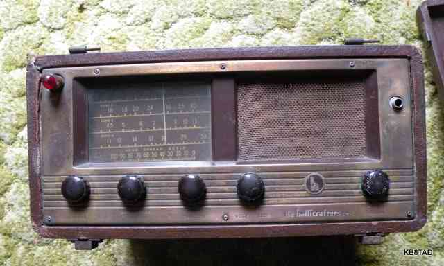
Condition as purchased
This S-72 was purchased at a swap meet. The power cord was cracked and bare in places, the bandspread pointer and dial cord were missing, and the front panel was dull and oxidized. The price was in accordance with the condition.
Schematic source and version
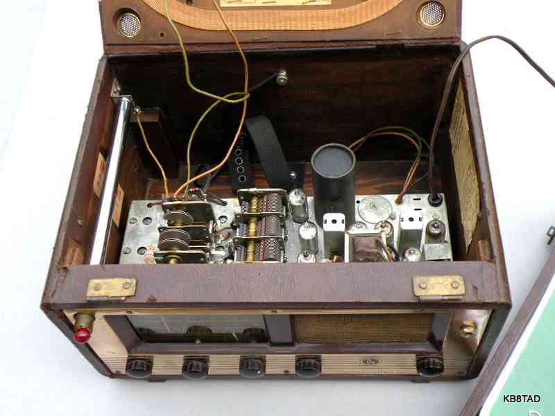
A manual and schematic are available from BAMA in djvu format. Pages from the Sams photofact are also on BAMA. I found an obvious mistake on the photofact. Sams indicates a current draw of 0.37 amps at 117 VAC. In later testing, I found that the set drew 0.22 amps at 117 which is in keeping with the 25 watts as specified in the Hallicrafters manual. I determined that my set was likely Run 4 which conformed to the manual on BAMA. An earlier version of the S-72 had a separate noise reduction switch on the front panel and located the bandspread capacitor on the underside of the chassis. My version places the bandspread cap on top of the chassis.
Repair notes
I replaced the power cord with a similar one. Because I wanted to maintain the original capability of plugging the cord into the battery changeover switch, I had to use a non-polarized older style cord. I used a permanent marker to indicate the side of the plug that I preferred to go to neutral.
The selenium rectifier had been replaced with a physically larger one earlier in the set's life. Masking tape had been used to keep the larger rectifier from touching the chassis. I replaced that rectifier with a terminal strip and pair of 1N4007 diodes in series, adding a 47 ohm resistor to make up for the more efficient diodes. The resistor was selected after powering up the set and determining a desired filament voltage of about 7 volts with 120 volts AC input.
As usual, I cleaned the pots and the bandswitch with deoxit. I checked voltages and replaced nearly all the wax caps in the set. Most other caps were ceramic and not showing any sign of leakage. The set was working with good sensitivity at this point. I located a suitable dial pointer and spring from the "boxe de junque" and replaced the missing bandspread dial cord with 65 pound spider-wire fishing line.
Alignment and sensitivity
I checked the oscillator alignment and accuracy of IF with a frequency counter. The alignment was mostly in good order, but I wanted top performance and so went through the detailed step by step procedure. The resulting final shortwave sensitivity of the set surprised even me. For final adjustment of the BFO, I tuned into the 80 meter ham band. With just the few inches of wire that connect the chassis to the telescoping rod antenna but without the rod or any other antenna connected, I tuned in several SSB conversations and tweaked the BFO for best reception.
External antenna connection
One of the wires from the terminal strip that feeds the loop and rod antennas was intended for an external long-wire antenna connection. That lead uses the 10K ohm resistor, also located on that terminal strip, which is probably for static discharge. My set did not have the wire which is shown in the schematic. I added a short one. For lack of a connector for the other end of that wire, I hooked it under the thumb screw that ties down the battery strap. I do not recommend connecting a ground wire because the set is AC-DC and uses floating ground. A capacitor-resistor combination is used to connect B- to the chassis. If you must connect a ground, I suggest using an isolation transformer for power or at the very least, using a small safety capacitor between the ground and the chassis. I used an isolation transformer when connecting my 80 meter ham radio antenna to chassis ground and the long-wire antenna pig-tail. That made for a fun afternoon of broadcast band DX-ing.
Performance
I am not the first to have noted that a properly operating S-72 will readily outperform a tube Transoceanic such as the G-500 or H-500 or for that matter, the later Hallicrafters TW-1000 or TW-2000. I'm left to wonder why Hallicrafters didn't simply adapt some of the S-72 circuit refinements such as separate mixer - oscillator tubes to a prettier cabinet design such as that of the TW-2000. They would have had obvious performance bragging rights in a three-way portable.
Follow-up questions
In the article, Hanlon comes to much the same conclusion as I did, that the S-72 is a much more capable radio than the competing Transoceanics.
The hole plug The bandspread cap change Model numbers Date 3-21-11, update 3-23-11
An Eico model 711 "Space Ranger" Receiver was the previous item on the bench.
Ed J. alerted me to a February 2010 Electric Radio article written Jim Hanlon W8KGI. Hanlon's picture labeled "figure 2" in that article answered my question about the missing "long wire antenna connector". It's apparently just a foot or so of wire with an unstripped loose end.
Ed J. also asked about the hole plug located next to the large electrolytic in all the pictured S-72 chassis I have seen. The hole plug covers an opening that would be appropriate for an octal tube socket complete with two rivet holes. Given the hole location and size I believe the hole was intended for a 117 volt tube rectifier as can be found in the Zenith 8G005 Transoceanic. I suspect that a reasonably-priced selenium rectifier came on the market just after Hallicrafters had the chassis metal cut. The other possibility was a plug-in ballast for 220 volt operation, but that is less likely since the manual specifically mentions a step-down transformer accessory available from Hallicrafters for that purpose.
According to the Rider's volume 20 information, the original bandspread cap in the S-72 was a compression trimmer. According to the Rider schematic, the trimmer only adjusts the oscillator and thus is not a true bandspread control for all three sections of the variable tuning cap as found in later sets. That early bandspread control also had a switch that was the "tone" control, switching in a small cap for treble cut. Later S-72 sets do not have the tone switch. A toggle switch for noise limiter was also part of early S-72 sets but was eliminated in later versions.
Hallicrafters also produced the S-72L with a VLF band in place of the highest shortwave band. A later version, the S-72R was apparently just a model name change rather than a major circuit change according to Chuck Dachis, author of the book Radios by Hallicrafters who could find no difference between the later S-72 and the S-72R.
Go back to the BA Pix Homepage.