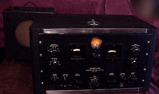
The Super-Pro series 200 is probably Hammarlund's finest prewar receiver. A full page ad introducing the SP-200 can be found in the October 1939 issue of QST magazine, page 73. An article on the new receiver appears in the November 1939 Radio News. The SP-200 sports 16 tubes on its chassis plus 2 in the separate power supply. Full page ads appeared in QST about once a month for an entire year. According to the November 1940 QST ad, "The fact that 'Super-Pro' receivers are used extensively by the U.S. Signal Corps and many other governmental departments, speaks for itself. Use the set the experts use." Newark Electric advertised the set for $279 in its Christmas 1940 ad, twice the price of the HQ-120X.
This SP-210-LX version has 5 bands, two of which cover VLF from 0.1-0.4MHz and three the shortwaves from 2.5 to 20MHz.
See also two military variants restored earlier, the R-129/U and the BC-779A .
Repair progress
This unit was purchased at auction with no power supply, no cabinet, no tubes or knobs and missing some of the shields. Knobs and tubes came from my "junk box". The bandswitch knob is similar in style but is not original. The front panel is in decent shape so I may just clean rather than refinish the panel. The set had many of its capacitors replaced by a prior owner. I have thus far been able to get it to partly work by connecting it to the power supply from a previously restored BC-779A. I will likely build a matching power supply for the set. Initial problems were a squeal (heterodyne) on stations which was traced to poor insulation on the grid cap lead of the oscillator tube, and a volume control with poor internal contacts, a problem cleared by an application of deoxit. Problems include non-working BFO and a sticky S-meter and noisy crystal filter control.
Progress report 1
The noisy crystal filter switch problem was solved by application of deoxit contact cleaner. Thought the BFO problem was due to the poor contacts on the oscillator switch. Removed the switch, found that I could squirt deoxit into the tiny holes in the front of the otherwise sealed switch. That solved the poor contact problem but not the dead BFO oscillator. Traced the circuit around the 6SJ7 oscillator. Found no screen grid voltage. The 500K screen grid resistor was open. Replaced it to restore the oscillator function.
Removed the S-meter from the housing. Carefully used small pieces of masking tape to catch the metal filings that had been attracted to the magnet and were interfering with the meter movement. Have to be careful with this operation as it is easy to damage the meter movement and its tiny springs. I will also clean the meter sensitivity control on the chassis.
After repairing the BFO and the sticky meter, took some time to listen the SSB transmissions on 80 meters. This receiver seems remarkably stable after a bit of warmup. Unlike its lower cost brother, the HQ-120, this set does not have a voltage regulator. Changing the input voltage 10 volts or so did not seem to affect the set at all. The alignment for this set also seems to be quite close for a long-dormant receiver. Will tweak it a bit. Have to be careful when aligning these sets, because like many of the era, the exposed IF adjustment screws on the input side carry high voltage B+. Always use a non-metallic or insulated tool for adjustment.
Progress report 2. Power supply.
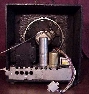
Built a power supply for the receiver by modifying a supply that had originally powered a tube-type Philco color TV. Re-used the power supply's original capacitors, choke, circuit breaker, diodes, terminal strip, soft-start thermistor, and portion of the chassis. Added bleeder resistors and changed dropping resistors to supply the proper voltage taps for the 100 and 250 volt outputs. Also added a small transformer for the needed -50 volt supply. Used a 12 volt half ampere transformer and reversed it, feeding the 12 volt side from a 6.3 volt winding on the TV power transformer. Added a diode, two caps and resistors to bring the result down to -50 volts at 5 milliamperes. The TV power supply works quite well, is a great deal lighter than an original, but barely gets warm in operation. I mounted the power supply chassis inside an older wooden speaker cabinet. The speaker is not Hammarlund but works well with a 600 ohm matching transformer. Used a wiring harness rescued from a defunct microwave oven with a multi-pin molex plug and jack to connect the power supply to the receiver's power supply terminals. The molex connector allows for easy disconnecting of the supply from the receiver. I used three wires in parallel for each filament lead to minimize voltage drop.
Progress report 3.
After further tweaking, found that this SP-210 is a nice peforming set on both international shortwave broadcasts and on ham bands on SSB. It is quite stable and sensitive given the vintage. Mounted it in a Bud cabinet which is a very close if not perfect match to the original.
Some specifications
All of the SP-200 sets are single conversion. The bandwidth is continuously variable from 3 to 16 KHz by a control which mechanically varies the coupling on IF transformers. A crystal filter allows even narrower bandwidths, down to "better than 1 Kc". Specified sensitivity is one microvolt. Audio power output is rated at 14 watts from push-pull 6F6 tubes with a third 6F6 used as the transformer-coupled driver. The sound from these sets is excellent with the proper speaker. Even a phono input is provided.
The Philips BX490A was the previous item on the bench.