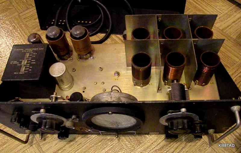
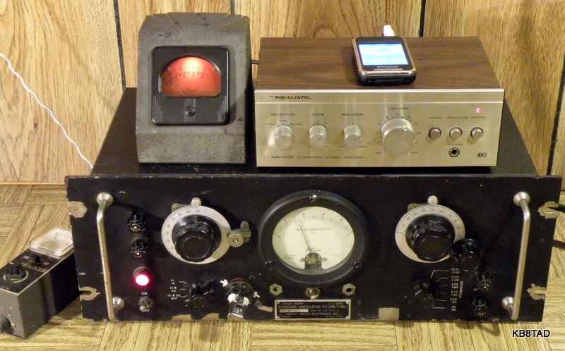
TS-39B as purchased
TS-39B/ TSM-1 military test oscillator
Repurposed as a part 15 broadcaster
What is it?
One of my ham radio swapfest friends said he had a device that had my name written all over it. He knows my interest in black wrinkle radio-related devices especially if they are heavy metal and military.
I asked "What's it do?". He wasn't sure. My curiosity was piqued. We agreed on a reasonable price. The Signal Corps nomenclature plate said TS-39B/ TSM-1 standard oscillator. It is serial number 5 so I assume very few were made.
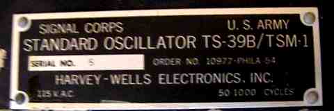
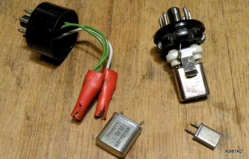
I was not able to find any schematic or other info on the web. A response on one of the forums decoded the TSM military number as Transportable Special Maintenance. The TS-39/U Standard oscillator was used to test crystals. It originally came with a couple of crystal adapters to plug into its front panel octal socket.
A relatively simple circuit
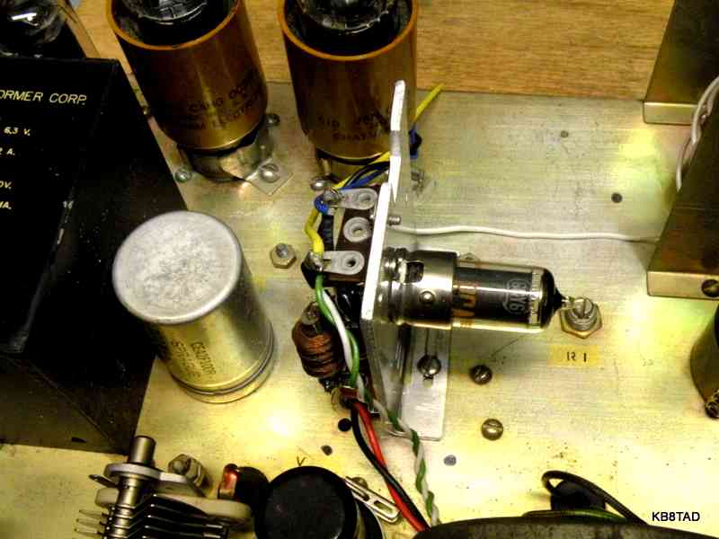
I studied the circuit inside. It has a 5Y3 rectifier and two 0C3 Voltage Regulator tubes in series for the power supply.
The entire active circuit is just one 6C5 triode as a crystal oscillator. A crystal is connected between ground and the grid of the 6C5. The plate is tuned by way of 6 bandswitched coils for overlapped ranges from 0.5 Mc to 30 Mcs (MHz) and a variable cap. The chassis-mounted meter has two sensitivity pots, one in series with the meter and one in parallel. The one in parallel had been turned to the grounded end, shorting out the meter. After turning both pots to center, the meter showed relative grid current through a grid-leak resistance which is in parallel with the crystal under test. There is no meter reading until the plate is tuned to resonance at the crystal frequency. The metered current varies with the relative activity of the crystal. A small variable and a small fixed cap can be switched in to add some parallel capacitance to the grid circuit.
An SO-239 connector on the back connects to a two loop pick-up coil for what I assume can be an output to an external receiver or frequency meter.
It works!
I cleaned the unit and made a couple of octal plug adapters for smaller crystals. Larger FT-243 crystals fit directly into the front-panel octal socket. Cleaning the sensitivity pots with deoxit stabilized the meter readings.
It was a useful device for its original purpose, testing crystal activity. I had fun with a 1 MHz crystal for which I was able to get the system to resonate at either 1 MHz or 1220 KHz. That was a unique function of that particular crystal since I had earlier gotten the same 1220 oscillation when plugging it into my grid dip meter.
A second use - repurposing as a broadcaster
The broadcast band resonance (at those 2 selectable frequencies) made me think of a simple part 15 AM broadcaster. There was plenty of room inside for a little added subchassis with a small RF power tube and Pi output as a MOPA (Master Oscillator - Power Amplifier). The voltage regulated B+ power supply and the filament winding had more than enough extra capacity for an additional tube at the 100 milliwatt input power for a part 15 transmitter. The original crystal testing function would still be available.
Broadcaster circuit
I tested a couple of different circuits but settled on one that has gained a lot of acceptance on the
Antique Radio Forum .
The circuit uses a 6GY6 or similar dual control pentode which is a tube with two input grids, one fed by a crystal-controlled oscillator and the other by an audio source for modulation. The circuit is capable of 100% modulation and shows a very clean signal on the oscilloscope when tuned and loaded properly. The circuit uses a small inexpensive integrated circuit 1 MHz oscillator identified as X1 on the schematic found at this link. The schematic is a current version by Tom B. using a 6GY6 and is based on an original design using another dual control tube, the 6888, by Norm L.
Dual control tube
The 6888 is a tube that according to its Sylvania data sheet is a "computer pentode designed for long life and low failure rate. It is utilized in pulse amplifier, core driver, and coincidence circuits". Other sources indicate dual control tubes used as dual input NAND gates.
I first came across the clever use of a dual control tube for RF and audio modulation in the Moss Electronics or Superior Instruments (SICO) Genometer TV-50 (not the 50A which is a different circuit.) SICO was known for using surplus tubes in their designs. The tube in the Moss and SICO TV-50 is a 6B1000 which I assume was a surplus computer tube when that signal generator was designed. At first glance, the 6GY6 and the 6B1000 may be plug-in compatible. I will have to check and verify to see if that is true. If so, the TV-50 itself may be a good candidate for conversion to a simple broadcaster. For follow-up; See the next item on the bench, the TV-50 Genometer.
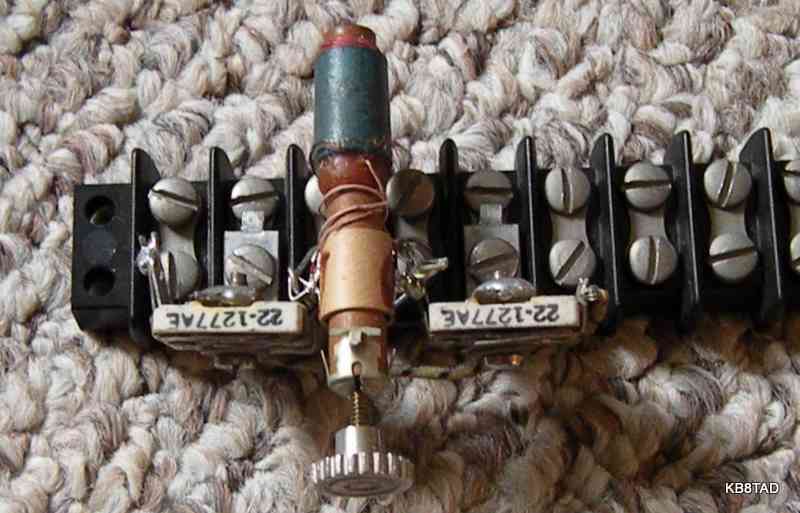
The 6GY6 subchassis
I used just the 6GY6 portion of the schematic noted above, eliminating crystal oscillator X1 since I already had a BIG crystal oscillator, the TS-39B itself. I obviously did not need the power supply section either. Also, since I planned to use an external audio amp, I did not need the 6C4 audio preamp tube. My circuit module starts at the capacitor labeled C-3 on the schematic for audio input to the 6GY6. The subchassis was built on a bit of scrap aluminum adding a tube socket and a pair of terminal strips. The result under going testing is shown in this picture.
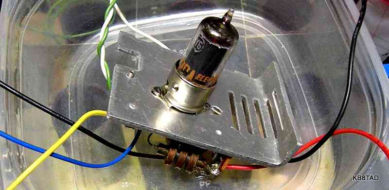
Note that the schematic shows an L-network for tuning (variable cap between output and ground and coil in series with the antenna). A Pi network adds another variable cap on the output side of the coil to adjust antenna loading. My Pi net consists of two small padder trimmers capable of about 50 to 500 pF each and a broadcast loopstick as the series coil between the two. The second cap for loading is recommended when using the full 10 feet of antenna. It also helps in harmonic reduction.
I replaced the old power cord with a 3 wire shielded cable with safety ground. The original unit had a fuse for each side of the power line. I rewired it to use only one fuse on the hot side with neutral going directly to the power transformer.
Operation as a part 15 transmitter
The FCC specifies that a part 15 broadcaster is limited to 100 mW input power and antenna length of 10 feet. The key to any of these broadcasters is proper tuning and loading. I used a scope to max the output. Signal input to the scope was with a short clip lead connected to the scope probe with a couple turns wrapped loosely around the antenna lead. Tuning and loading is quite sharp with just a quarter turn in either direction of the peak dropping the signal level noticeably on the scope.
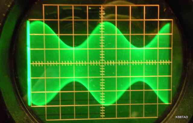
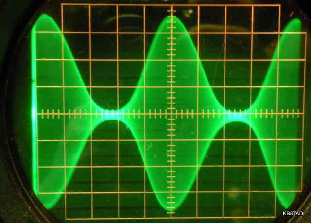
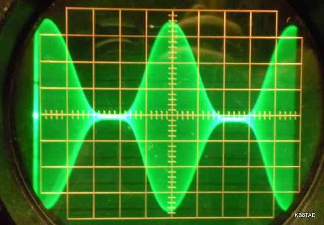
Modulation percentage
To prove the full modulation capability, I fed the broadcaster with a 600 hertz audio signal. One hundred percent modulation could be achieved with a 1.5 volts RMS signal. Here are several scope images of its modulation envelopes.
Using the Broadcaster
The little transmitter is capable of a decent signal level to any AM radio in my two-story house as well as unattached garage. I feed the broadcaster with an external Radio Shack stereo amp. The amp when switched to monaural does the channel mixing and feeds the 6GY6 directly from a speaker output. The second speaker output is used for an outboard VU meter for modulation level as matched by the oscilloscope. I use an MP3 player as program source. It's fun to use antique radios to listen to my favorite music. The 6GY6 in the TS-39B makes an excellent AM broadcaster.
Date 1-11-11
An AN/GRC-109 Special Forces radio set, a rebadged CIA radio set, was the previous item on the bench.
Go back to the BA Pix Homepage.