TV-50 Genometer ad on back cover of July 1956 Popular Electonics
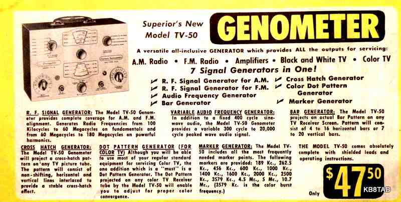
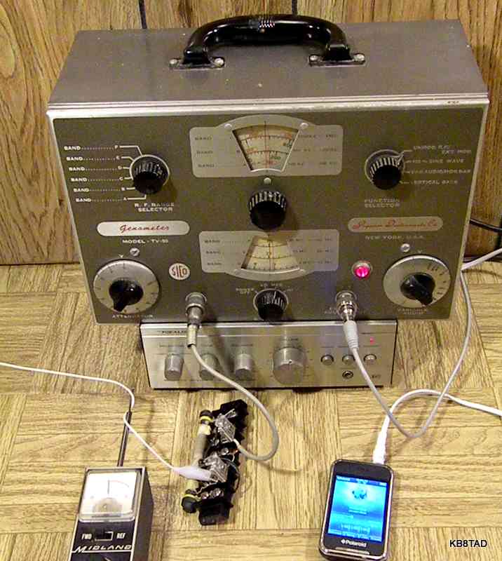
Superior Instruments Genometer TV-50
repurposed as a frequency-agile AM modulator / broadcaster
Another part 15 broadcaster
In the previous item on the bench, I added a little AM modulator chassis to a military crystal tester. That worked well using a circuit that has become very popular among
Antique Radio Forum (ARF) members. These excellent little broadcasters all use dual-control tubes, mostly pentode but some heptode.
While the circuit works great for frequencies for which I had crystals, I really wanted to listen to the lower part of the broadcast band, between 600 and 800 KHz. I did not have any crystals in that section of the band so was looking for a solution that would allow me to vary the frequency.
Hype and the TV-50
I have always considered the Genometer TV-50 by Moss Electronic Dist Co. Inc (MEDCO), later known as Superior Instrument Company (SICO), to be one of the most over-hyped general purpose signal generators ever designed using cheap surplus components wherever possible. The ads on the back of electronics magazines tout all sorts of capabilities in a signal generator with just two active tubes and a rectifier. (Note that my comments and the broadcaster conversion apply only to the TV-50, not the later TV-50A which is a much different circuit.)
but Moss got this part right!
The Genometer TV-50 was my first exposure to the use of a dual control tube for modulating RF. The tube in the Moss or SICO TV-50 is a 6B1000, an oddball 7 pin miniature tube which was surplus when the signal generator was designed (the schematic drawn by J. Moss is dated 1954). The 6B1000 was likely a tube used by IBM in early versions of its 604. IBM used the generic number of "6B" to refer to its dual control sharp cutoff heptode that was based on a modified 6BE6.
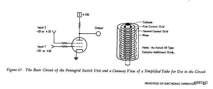
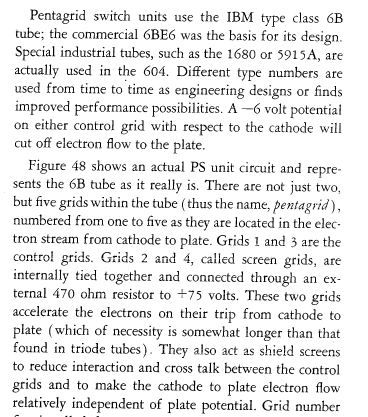
IBM worked with tube manufacturers and also designed some of its own tubes. There are similar tubes with the same 6B prefix and a different 4 number suffix so I assume IBM kept improving their 6B until commercial tube manufacturers could meet their specifications. The manual for IBM's last 604, model 604E, is dated 1958. In that manual, IBM still describes the circuit as a 6B tube and notes then-current tube numbers as a commercial 5915A or 1680 (the 1680 is noted by some sources as an IBM 6B3001). As noted below by IBM, the dual control 6B tube series allow the tube to be cutoff by either grid at -6 volts.
Pin compatibility
The 6B1000 pin-out is the same as nearly every other 7 pin miniature dual control heptode. Dual control pentodes are also pin-compatible and can plug directly into the same socket.
With total pin-compatibility, I decided to use the TV-50 as a platform for experimenting with tube swaps such as the 6GY6 and 6AS6 and possible conversion to broadcaster.
TV-50 repairs
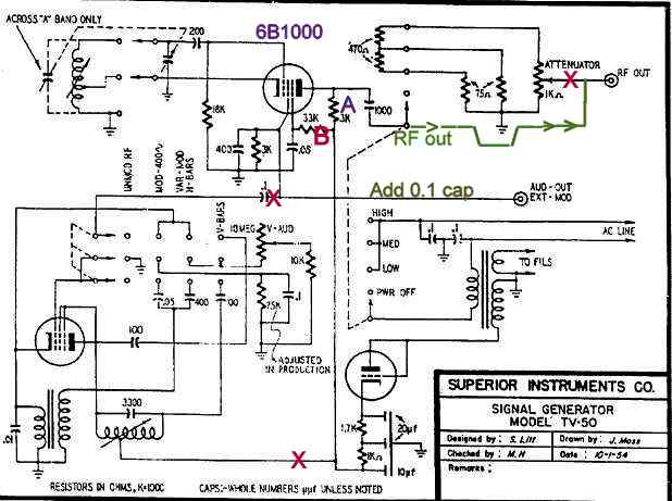
As with any restoration or repair, I replaced the leaky capacitors in the TV-50 RF circuit at the screen grid and plate of the 6B1000 RF tube. I replaced the old power cord with a shielded 3 wire grounded cord and removed the two 0.1 caps from the power line to chassis which I determined were not necessary for my purposes and with a safety-grounded chassis.
TV-50 conversion to broadcaster
I pulled the audio oscillator tube (lower left on schematic), since I did not need it for the broadcaster conversion. That tube is either another 6B1000 wired as a triode (in earlier models) or a 5844 duo-triode computer tube (later models).
Since the audio input line did not have a capacitor between the external modulation input jack and the audio input grid of the 6B1000, I added a 0.1 MFD cap in that line (See note in green on schematic) and cut out the one that came from the existing audio oscillator. (See red "X" on schematic). The rectifier tube in the TV-50 is a surplus 7193 VHF triode repurposed by Moss as a half-wave rectifier. I could have replaced it with a cheap 1N4007 silicon diode and a resistor, but it and the large oversize electrolytic were working very well so I simply left them in place. B+ was measured at 170 volts, about right for the broadcaster circuit.
The ARF circuit mentioned previously used a 1 mH choke in the plate feed. I removed the 3K ohm plate resistor (purple "A" on schematic) and replaced it with the choke. I bypassed the RF attenuator switch and directly connected the RF output from the 6B1000 plate by way of its 1000 pF cap to the RF output jack (Green line on schematic).
Pi-net output
I used an external pi-net circuit for broadcast-band resonance. The pi-net consists of two compression trimmer caps with a 50 pF to 500pF range on either side of a ferrite broadcast antenna donated by a junk radio, mounted on a barrier strip.
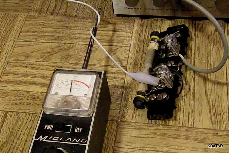
The caps can be adjusted to select a frequency for resonance in the AM broadcast band. Resonance at any selected frequency is quite sharp. I again used my oscilloscope to view the waveform. The scope probe was connected to a clip lead that was loosely wrapped around part of the ten feet of antenna. Since the TV-50, as an RF signal generator, was itself supplying the RF, I could re-tune it to see where my pi-net was resonant and then gradually retune the pi-net caps to move the resonant point to the frequency of interest. I found a problem that was caused by the little choke I had placed in the 6B1000 plate feed. That choke and stray capacity caused a low-frequency RF resonance all by itself. A harmonic of that self-resonance interfered with the ability to maximize output at my desired frequency. I replaced that choke with one I had liberated from the circuit board of a burnt-out CFL bulb. That second choke, a little cube-shaped ferrite inductor, had the same inductance but obviously much lower "Q" than the choke I originally used. Swapping the choke solved the problem.
Maximizing output
The original screen voltage for the 6B1000 was 68 volts. I tried increasing the screen voltage on the 6B1000 to maximize the RF output as seen on the scope but the increases were only marginal and I was afaid of damaging the tube.
I then swapped the 6B1000 heptode for a 6GY6 dual control pentode and tried the same thing. The output actually REDUCED when I increased the screen voltage. Therefore, I decided to reduce the screen voltage to see what would happen. The output INCREASED! In fact, the output increased substantially until the screen voltage was lowered to about 35 to 40 volts. Below that optimal screen voltage, output dropped again. I next substituted the 6AS6 dual control pentode. Its optimal screen voltage was nearly the same as that of the 6GY6. Both tubes worked well. The maximum output for either of the substitute pentodes was significantly greater than what I had experienced with the 6B1000 so I decided to change the screen resistor (labeled "B" on schematic) to reduce the screen voltage to that optimum point. In actuality, I simply added a 10K resistor between the screen grid and ground leaving the original 33K screen resistor in place. The two resistors make a voltage divider which along with the screen current dropped the screen voltage to about 38 volts.
I suspect that the screen voltage versus output results could serve as an easy way to tell if an unknown dual control tube is a heptode or pentode.
I kept the 6AS6 in the TV-50 because I had several spares of that number but only one 6GY6. Full modulation could be achieved with only 3 volts RMS audio. The full-modulation scope display was very clean. I use a small Radio Shack audio amp to supply the 3 volts RMS from a speaker-level output. The external amp does the job of amplifying and mixing the stereo channels from my MP3 player which is used as the broadcaster's music source.
The TV-50 with the 6AS6 stays relatively cool. The frequency drift from cold to warm-up is negligible. Although not as powerful as some other small broadcasters I have experimented with, the quality of output is excellent and meets my need for a frequency-agile broadcaster. Modulation to 100% can be easily achieved and hum is nearly nil. As in all broadcasters, the tuning and the "Q" of the pi-net (or L-net) is critical for maximum output.
The short antenna and the pi-net are in fact one tuned circuit. Any changes in antenna length (10 feet maximum) or nearby metal, etc will detune the system. Once set up, the system is very stable. I use a little signal strength meter from the CB era to check signal strength at my desired frequency.
Possible future modifications
The audio section inside the TV-50 could easily be reworked as an audio preamp. A 6C4 could easily be added as shown in this schematic and writeup from Mike Yancey on the earlier version of the dual control tube ARF broadcaster . Even the existing audio oscillator tube in the TV-50 (6B1000 as a triode or 5844) could be readily re-purposed as a triode audio preamp.
The ARF discussion of the most recent homebrew broadcaster with a dual control tube can be found here. The latest version of the broadcaster uses a dual control tube and audio preamp with filaments that allow the use of inexpensive surplus power transformers. Here is link to the schematic of the most recent ARF broadcaster
Low impedance in the audio feed line is important for minimizing RF pick up by the audio line according to experimenters at the RadioMuseum.org who suggest a cathode follower for audio for low impedance feed. I agree but that is all the more reason to keep using my speaker-level audio feed which is of course very low impedance.
The 7193 rectifier can also easily be replaced as already noted. That would free up an octal tube socket and the power for one filament.
In the moment, I'm satisfied with the simple modifications of the TV-50 and am enjoying the music.
Date 1-26-11, updated 3-28-13
A TS-39B/ TSM-1 military test oscillator, repurposed as a broadcaster, was the previous item on the bench.
Go back to the BA Pix Homepage.