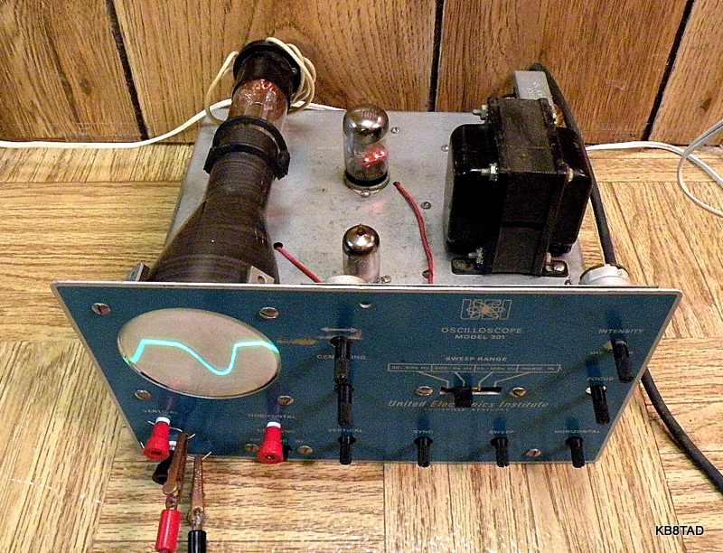
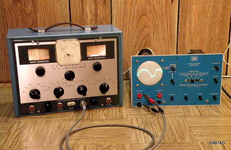
UEI 301 Scope meets Radio Shack TK-100 signal generator
The scope shows Louisville, Kentucky as the home of UEI which was also known earlier as United Electronics Laboratories (UEL). The school offered a diploma for electronic technician training in Louisville and several other cities as well as some home-study courses. UEI / UEL also designed radio kits and a vacuum-tube voltmeter. All the kits were integrated into course lessons and assembled by the students as part of course work. Click on this link for a full description of a UEL broadcast radio kit.
Repairs
This scope worked as obtained. With a few exceptions, the capacitors in the set were quality components and did not need replacement. Since this was a kit, I checked the wiring and soldering carefully. I cleaned the controls with deoxit and the chassis with white waterless hand cleaner. This was followed by safety checks and tracing the power supply circuit so I could monitor B+ and other voltages when powering-up the set slowly with my isolated variac. All appeared to be in good order. I noticed in various traces that the horizontal amp seems to be a bit non-linear but do not know whether that is due to the design or whether there is an actual electronic fault. I did not have a schematic for the initial testing and repair. With the schematic now in hand, I can check further. The flat-topping vertical distortion of the signal as pictured was due to the TK-100 signal generator and was corrected as noted below.
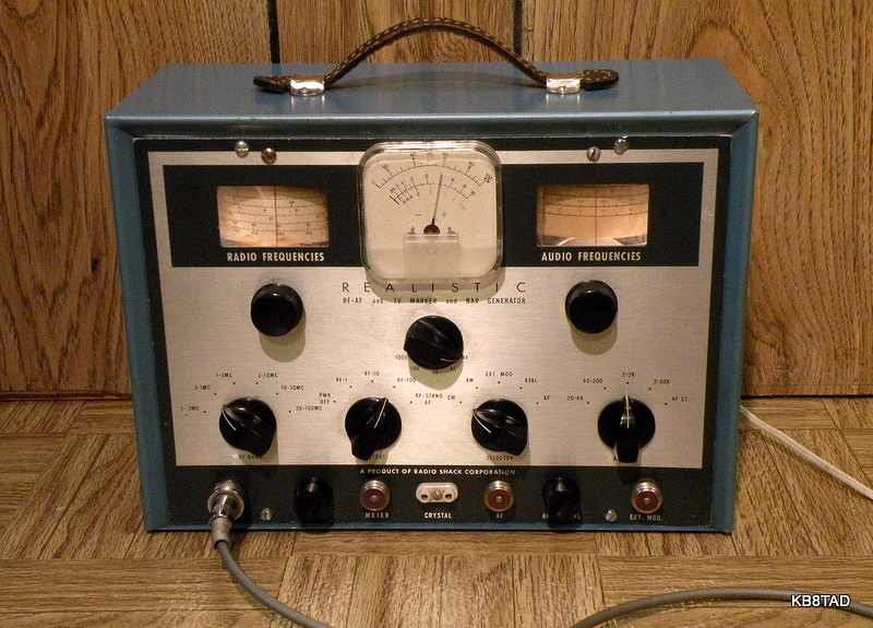
Radio Shack TK-100
The TK-100 was a signal generator kit offered by Radio Shack in their 1962 catalog. It was also available as the TW-100 factory wired version. Price of the kit was $49.95. It combined an RF generator and a variable audio generator with an AC meter that could read the audio or RF output levels or be used directly via a front panel input. The generator includes provision for internal modulation of the RF by the AF generator or external modulation input enabling use as a simple low powered broadcaster.
Repairs
The RF section of the signal generator worked but not the AF. I replaced the leaky 0.1 MFD caps in the audio side, but that did not solve the problem which turned out to be a shorted bulb socket in the Wien-bridge cathode circuit. The plastic control shaft that turns but insulates the AF variable cap from ground was cracked at the set screw hole. I used cyanoacrylate glue to repair the break and reinforced the plastic shaft with two loops of bare solid hookup wire that was tightened and then soldered for strength. I also had to restring the dial cord on the RF side.
The somewhat distorted audio waveform as pictured on the UEI scope screen was later corrected by adjusting the chassis-mount potentiometer on the TK-100 that controls feedback level. I also tested the external modulation input by feeding an MP3 player to it via a matching transformer. It works as well as other service-grade signal generators I have tested.
Schematic and documentation
I did not have a schematic for the TK-100 when repairing it. More recently, Steve B. wrote and generously offered me a copy of the schematic as well as a page with the voltage-resistance chart. Send a note to my e-mail address on the home page if you need a copy of the schematic and chart.
The Radio Shack catalog information on the TK-100 can be found in the Radio Shack catalog archive .
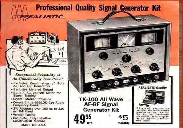
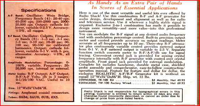
The 1962 catalog ad on page 17 has a good desription of the instrument. The instrument is also advertised in the 1963 and 1964 catalogs. The 1964 price dropped to $39.95 and the item is no longer listed in the 1965 catalog. The catalog ads contain some hyperbole. According to the catalog, the generator offers "amazing versatility at an unbelievable low price".
The ad claims a "2% accuracy over the 100 Kc to 330 Mcs RF band". I consider that claim to be somewhat exaggerated unless the unit is calibrated very tightly.
"Exclusive metered output." The built-in AC volt/ db meter is said to be for signal tracing. It is useful as an output meter when aligning sets.
Like other service instruments in its price class, the instrument is useful for general purpose radio alignment if teamed up with a frequency counter or digital-tune radio to verify accuracy. I like the separate lighted dials for AF and RF as well as the amplified external AF input provision. The crystal marker provision is also a nice touch.
12-26-09; updates 3-15-10 and 3-22-11
A Grommes 260A Circuit in a HomeBrew Audio Amp was the previous item on the bench.