I have used a variety of Vacuum Tube Volt Meters (VTVM). While digital meters have their place, the VTVM has uses for which digital meters fall short. The typical service VTVM such as those made by Heathkit measure DC with an input impedance of 11 megohms on all ranges. Variations in voltages are more easily followed on an analog meter. Low resistance can be measured without regard for the resistance of the test leads or connections.
Blowing out the Beckman
I came back to using analog meters as my primary tools several years ago after blowing out my expensive Beckman digital meter. I was measuring the no-load voltage of a power transformer. The measured voltage was only about 600 or so. I had safely attached clip leads onto the transformer before applying power. When the job was completed, the simple act of unplugging the transformer blew out the meter. Yes, you guessed it. The collapsing field of the unloaded power transformer put a flyback high voltage pulse into the Beckman sending it to its digital demise. I now use a VOM for such AC measurement. For DC measurement in high impedance tube circuits, however, the VTVM is preferred.
Heathkit VTVMs
Heathkit made a number of VTVM models. Judging from the ones I see at ham radio swap meets (called "hamfests"), Heath probably sold more VTVMs than any other manufacturer.
All the Heath VTVMs have a near-identical circuit that uses a dual-triode 12AU7 with the cathodes feeding the meter for balance with potentiometer adjustments to set the zero point and the voltage calibration. The basic measurement range is full-scale at 1.5 volts (3 volts in some older models) with precision resistors switched in for higher ranges. A 6AL5 is used as rectifier for AC measurement. The earliest Heath VTVMs such as model V4A (in group pic below) use octal tubes with a 6SN7 in place of the 12AU7 and a 6H6 in place of the 6AL5 but the circuits are essentially the same. The ohms ranges use a 1.5 volt battery, typically a "C" cell. The oldest Heathkit VTVMs use 3 volts from a pair of "D" cells in series.
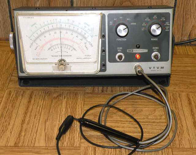
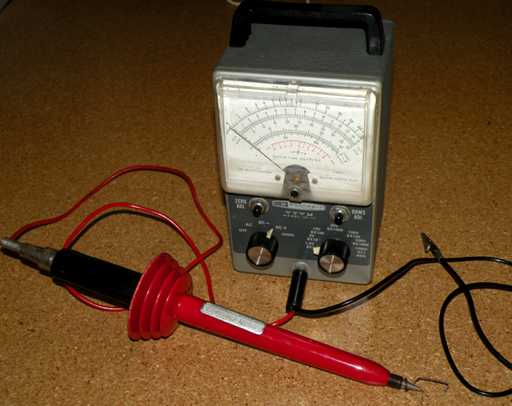
This Heathkit IM-13 VTVM is a low-profile bench model. It was in good cosmetic condition and came with the proper Heathkit probe. It did not work but was definitely priced right. I find it difficult to resist a repair challenge especially if the price is right.
Repairs
The meter movement inside the typical Heath VTVM is 200 microamps. I used the highest resistance range of my VOM (my work-horse Triplett 630A) to see if I could get the meter to move. The VOM is rated at 20,000 ohms per volt with a meter that is 50 microamps full-scale. The VTVM meter movement went upscale about a fourth of the way indicating it was good.
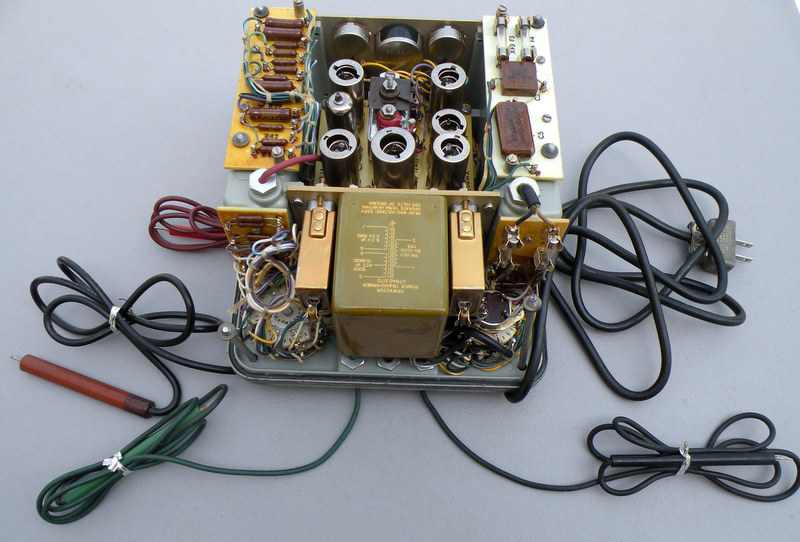
After safety checks (checking for AC line leakage to chassis), I powered the VTVM and measured the B+ across the electrolytic, again using my Triplett VOM and clip leads. It came up quickly to the right voltage. However, the voltage did not drop very quickly when I unplugged the VTVM. This was my first clue. The VTVM was not drawing power.
Looking at the schematic, I saw that the power supply feeds three resistors with a voltage divider to ground. The resistors tested fine. And then I saw the problem. The wire from B+ going to the terminal strip with the three resistors had never been soldered. Even though the wire appeared to be touching the terminal, it was not making contact. I suspect that this VTVM may have been intermittent for much of its life and probably quit after being dormant for a time.
A typical kit problem
I have seen this problem in other kits. Heath instructions would direct the builder to add several components to a point on a terminal strip and then finally direct the builder to solder that point. However, sometimes the solder did not make it to all the wire connections. I checked the other terminal strips and points with multiple wires and found another unsoldered wire. Resoldering solved the problem. I followed up by applying a bit of deoxit to the control pots and checking their function. Upon power-up, the VTVM came to life, and I was able to calibrate it.
Battery for ohms
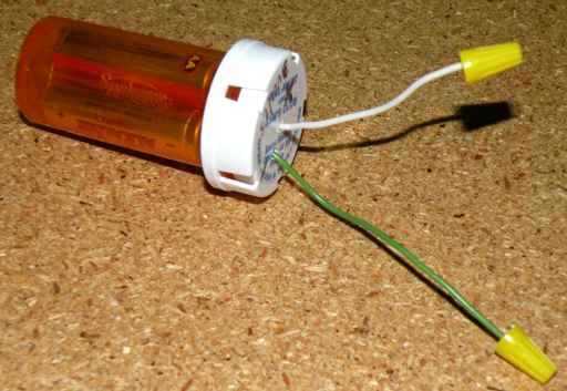
As noted, these VTVMs use a battery for the ohms function. The typical battery in a Heathkit is a "C" cell mounted in a copper spring. That spring makes the contact from chassis ground to the negative side of the cell. It is also easily corroded. If the spring shows a bit of green on it, the contact is poor. Even a bright copper spring will sometimes not make good contact with the bottom of the battery. If the ohms function does not work or works at the highest ranges but is far from accurate at the lower ranges, the battery is not making good contact. I clean the copper spring and then use a file to scrape away any remaining corrosion. In difficult cases, I simply wire the battery in place. A pill bottle with one or two alkaline "AA" batteries inside wired to the VTVM will solve the problem and contain any possible future corrosion leakage within the pill bottle. An alkaline "AA" or a pair in parallel should easily outlast the original carbon-zinc "C" cell. Another option is to make a simple 1.6 volt DC source via the filament supply and a three terminal regulator chip such as the LM-317.
That probe
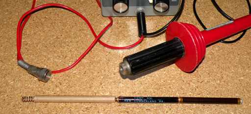
This Heathkit came with the switchable single probe for DC and AC/Ohms. For such a probe, I always check both ends for properly soldered connections. The probe itself contains a 1 megohm resistor that is required for DC measurement. That resistor is shorted out when the probe is set for AC and Ohms.
If the probe is missing, I recommend modifying the VTVM to that of an earlier model that did not have the combination probe. Older Heathkits used separate jacks for DC, AC and ground. A replacement DC probe should maintain the 1 megohm resistor at the tip so that sensitive high impedance circuit measurements see minimal loading.
The round-up
Once the IM-13 was working properly, all the other VTVMs in the shop wanted to shake prods with the new member and get their controls cleaned and batteries checked. All of them joined in for a group photo.
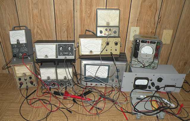
Although his battery connector was never corroded, the Heath V4A did not want two fat heavy expensive "D" cells but opted for a pair of slim "AA" cells in a pill bottle instead.
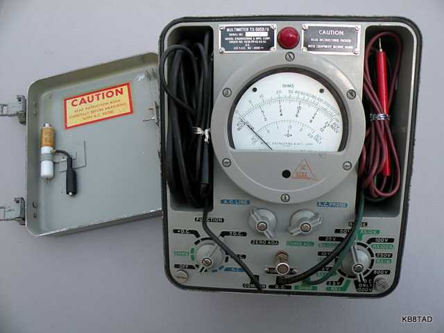
The big RCA WV-87A bragged about having a third vacuum tube, one more than the Heathkits, but kept quiet after the Tech Sergeant (TS-505D/U, retired Signal Corps) mentioned that his chassis had 7 tubes and none of his probes get lost because they are all permanently connected.
One of the Heathkit IM-11 twins showed off his big red Heathkit high voltage probe and mentioned that although it was designed for up to 30,000 volts DC, it could also could be used on ranges such as the 1.5 volt scale for voltages up to 150.
The Heath high voltage probe impressed even the Hewlett Packard HP-410B who has his own web page. He can't use the probe but admires its simple and colorful design.
Much more info on VTVMs
One of the VTVM group's favorite web sites for info on VTVMs is the "Tone Lizard" site which specializes in guitar amps. That site also has the group's vote for best "tip of the day" with the sugestion to use the spring from inside an old flashlight as the replacement for a corroded battery spring for Heathkit VTVMs.
Calibration.for Heath VTVM
Basic calibration for DC for a Heath VTVM was based on the fresh new single cell carbon-zinc battery having a voltage of 1.55. Most Heath VTVMs have a small red dot to the right of the 1.5 volt scale which is the calibration mark when reading the voltage of a new cell. A new alkaline "AA" will read just a tiny bit higher, just shy of 1.6 volts but close enough for the 3% accuracy of a VTVM. The VTVM shines on measuring high impedance tube circuits where loading the circuit is an issue but 3% accuracy is not.
For AC calibration, I used a 12 volt transformer with a no-load voltage of 14 and compare the reading with a known accurate meter. Calibration is on the VTVMs 15 volt scale.
My VTVMs also suggest a free booklet (now a 13.3 Megabyte free PDF) put out by Sylvania back in the 1950's entitled "Servicing Radio and Television with a Vacuum Tube Voltmeter" . The PDF is one of several publications in English hosted at a French site
.
Notes and updates
An excellent schematic for the TS-505D/U can be found at this link.
The TS-505A/U manual is available at BAMA in its military manual section. See home page for a link. It is close enough to the TS-505D/U for most purposes.
4-24-09; update 12-09
A National CRM oscilloscope with a 1 inch screen was the previous item on the bench.