The tubes in the set are all 8-pin rimlock style. Those are like American 7 pin miniature tubes but have an eighth pin where the American tube has a space. A dimple is added to the glass base (earliest tubes had a metal ring with dimple) and a guide path is provided in the tube socket to assure correct placement. The tubes are ECH42 as oscillator-mixer, EAF42 as IF amp, EBC41 as detector and AVC, EL41 as audio output, and an AZ41 rectifier.
Condition
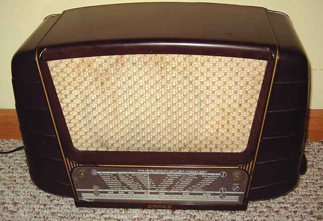
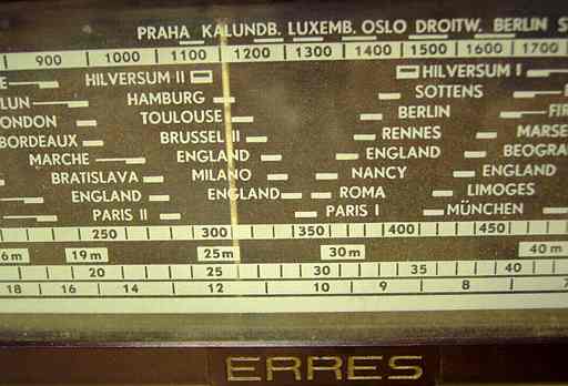
I bought this set in Doorn, the Netherlands, at a swapmeet sponsored by the NVHR, The Netherlands Society for the History of Radio. As purchased, it was connected for European 220 volts. Part of the appeal for a US buyer was the voltage selector. This radio can easily be reset for a variety of voltages. I reset the input to 125 volts and replaced the European power plug with an American standard. The cosmetic condition of this set was good as purchased, but was missing the cardboard back and bottom, a common problem in European sets. No obvious work had been done on the set. All of the alignment adjustments still had the original factory paint seals. The bruise to its plastic tuning scale on the lower left side was caused by careless repacking after an airport inspection in the USA.
Repairs
I did not have a schematic but the circuit is a fairly straightforward superhet. Once the tube functions and pin-outs are known, the circuit is not overly complex. I used Frank's on-line tube manual (see link on the home page). On pulling the tubes to verify their numbers, I noticed that the tube pins looked rather oxidized. I sometime use a soft brass bristle brush along with contact cleaner to clean tube and plug pins. The brass brush helped to brighten the oxidized pins. Contact cleaner was also applied to the tube sockets and controls. Before applying power, I checked the B+ line with an ohmmeter for a normal high level of resistance. I also checked for any line to chassis leakage. All appeared fine.
I plugged an antenna, just a short hank of wire with a banana plug, into the antenna jack. I then slowly powered up the set with my isolated variac while monitoring B+ voltage and current consumption. All appeared normal. Surprisingly, the set started making some AM noise. After I tuned the set a bit, it was playing a local broadcast station. The local airport beacon could be heard on the LF band. However, the B+ was somewhat erratic, hovering between 220 and 250 volts.And then suddenly the B+ dropped to zero. The AC current draw also dropped indicating that I was probably not dealing with a short circuit. I noticed that the filament glow on the rectifier tube was no longer visible. The rectifier tube is mounted horizontally above the chassis with the socket assembly bolted to the power transformer. Wiggling the tube caused the B+ to return. The soldered connections and wires were intact. The problem was poor tube socket contact. Further cleaning of the rectifier socket contacts solved the problem.
I checked several of the capacitors in critical circuit locations for leakage (such as the input grid to the audio output tube). The caps were found to be in good order.
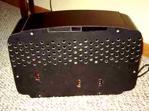
The missing back and bottom.
In contrast with typical transformer-operated American sets, a back is necessary on European sets because exposed high voltage contacts can often be found above the chassis. This one has the rectifier socket and power transformer input connections exposed.
As far as I know, there are vendors in Europe who sell reproduction cardboard backs and bottoms for a number of antique radios. Not having ready access to a reproduction, I cut a back for the set from the hardboard back of a discarded TV set adding holes for the three dual-banana-plug jacks typical of European sets. Those jacks are for connecting an antenna and ground, a phono input, and an external speaker.
Performance
This set has no RF amp. I found it to be quite sensitive, on a par with the best of the typical 5 tube American sets. With a proper antenna, it is a very good performer. It easily picked up my favorite distant (and weak) daytime oldies station, a subjective standard I use for a sensitivity test for AM broadcast.
Other European sets
I have repaired other sets of European manufacture. A couple of examples can be viewed here; Philips BX-490A and Nordmende-Sterling Tannhauser .
More info on Erres
Click here for information on Erres and pictures of Erres radios by John Hupse in the Netherlands.
A Gonset Commander II transmitter was the previous item on the bench.