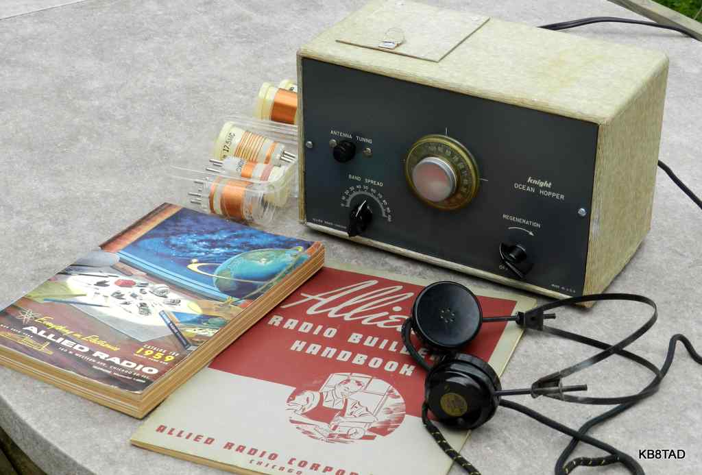
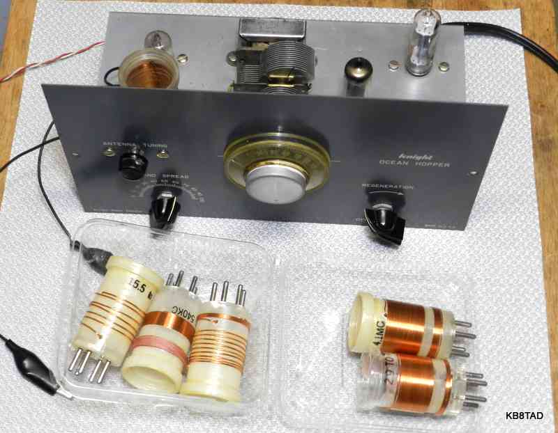
This Knight Ocean Hopper receiver from Allied Radio is a three tube regenerative set covering the broadcast band. Five plug-in coils sold separately increase the coverage from 165 KHz to 35 MHz. Tubes are 35W4 as rectifier, 50C5 for audio output and a 12AT6 triode as the regenerative RF detector. The radio has screw connections for an external speaker, pin jacks for headphones, and a fahnestock clip for antenna connection.
Regenerative radio
Regenerative circuits, discovered by Edwin Armstrong, date back to the very beginning of vacuum tube radios. The Ocean Hopper differs from the earliest circuits mainly in the choice of how regeneration is controlled. This Ocean Hopper's regeneration control is a variable resistor which variably shunts (shorts out) the RF energy on the feedback winding on the 12AT6 plate. That winding is traditionally called a "tickler" winding and feeds back a bit of the amplified tuned signal to the tube's grid. Too much regeneration is a bit like holding a public address microphone too close to its speaker, resulting in a squeal of positive feedback. The same effect occurs at radio frequencies but just prior to that squeal, the regenerative circuit has tremendous amplification and narrow bandwidth.
Like most similar sets, the Ocean Hopper has four controls, three of which are variable capacitors. The main "Band set" variable capacitor sets the approximate tuning range. The smaller 15 pF bandspread cap tunes a small portion of that range. An even smaller variable cap of 3-30 pF is used as an antenna trimmer. The fourth control is a variable resistance to control regeneration level combined with the power switch.
AC-DC power supply
The Ocean Hopper's power supply is transformerless AC-DC using one side of the power line as floating B- with a 0.05 MFD capacitor and 270K ohm parallel resistor between the power line B- and the chassis. That introduces some safety concerns although the floating B- is a lot safer design than directly placing the chassis at B- as was common in the regenerative radio sets offered by Meissner or the ones built through Progressive Edukit. Solutions to improve safety are detailed below.
The "Ocean Hopper" name
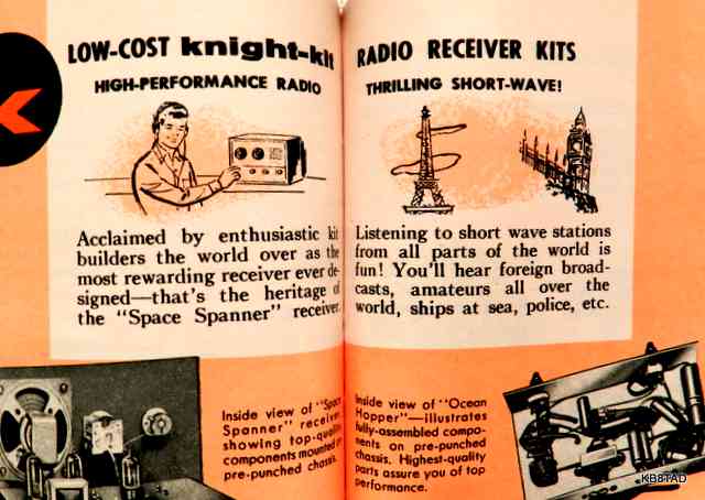
The name "Ocean Hopper" predates its use by Allied Radio. It was an imaginative name dating back to the early 1930's for radios that could indeed "hop oceans". Listening to short wave signals from distant foreign countries that crossed the oceans by skip signal was a new experience for many.
Allied Radio's original "Ocean Hopper" was a two tube kit. Here is an ad from the October 1941 Popular Mechanics magazine.
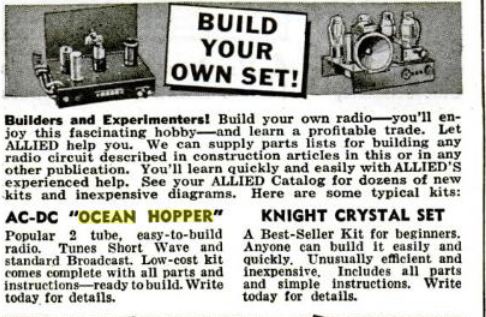
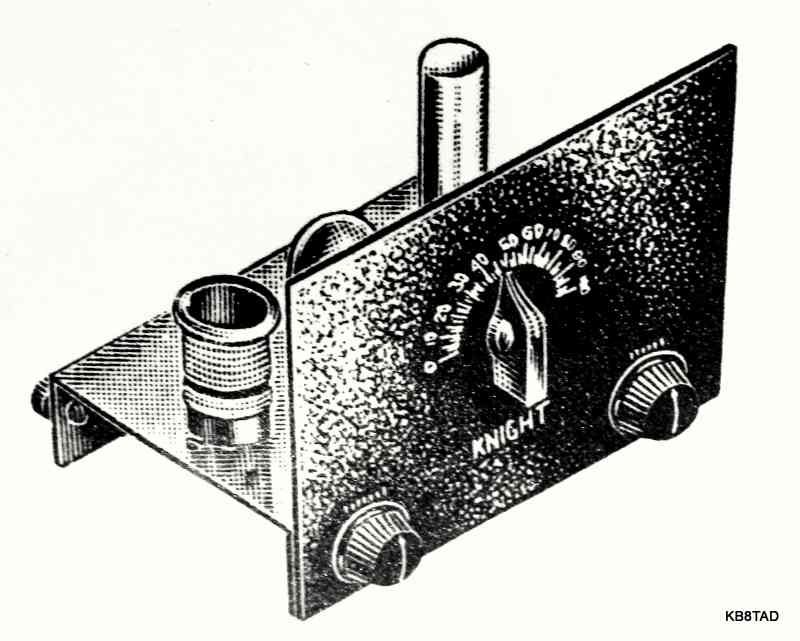
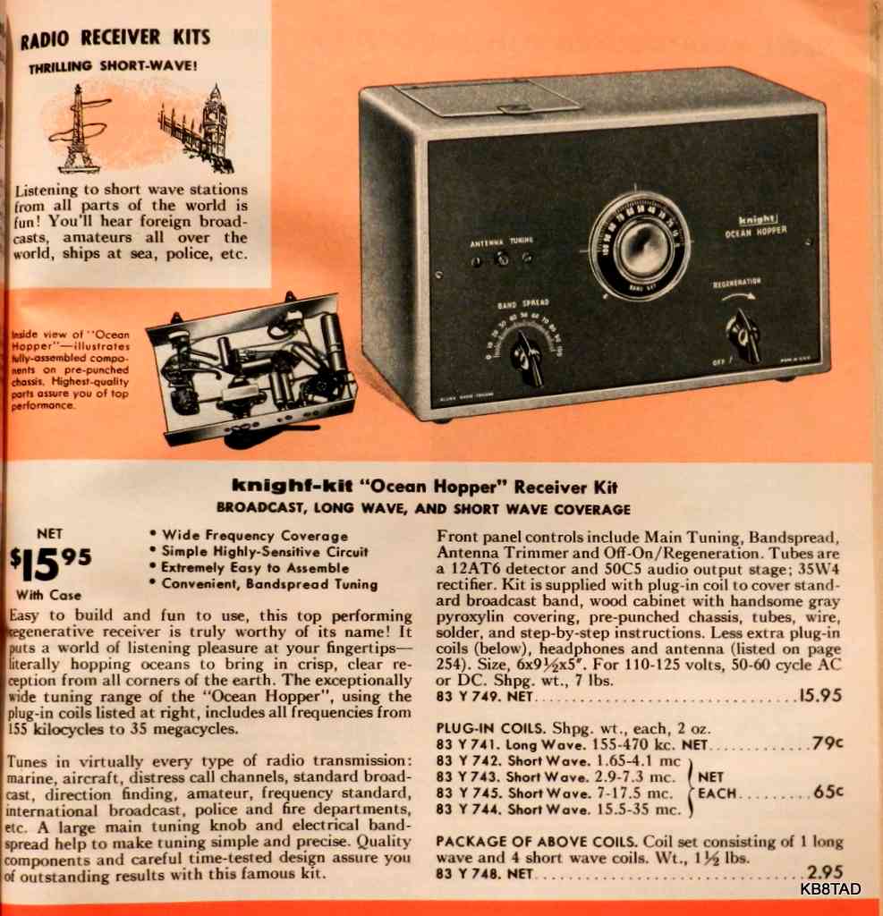
As shown above, the first Ocean Hopper had a chassis and front panel but no cabinet. It was offered until 1953 when Allied introduced an Ocean Hopper with 3 miniature tubes, model 740. The 740 was also sold without a cabinet. An early 740 can be identified by its lack of the two holes on the left and right of the front panel which are for the screws to attach the panel to the cabinet.
This version, model 749, was sold with the cabinet, but its circuit is the same as the 740. A later variation of the 749 eliminates the power supply choke, replacing it with a 680 ohm resistor and increasing the high voltage electrolytic cap sections from 30/30 to 40/80 MFD. Both the 740 and 749 improve on the original 1941 Ocean Hopper by combining both sections of the bandset variable cap for the VLF and Broadcast coils. The 1941 model with its 140 pF bandset cap requires two coils to tune across the broadcast band.
Ocean Hopper 749 as acquired
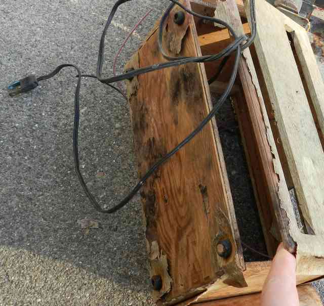
I had been looking for an Ocean Hopper ever since passing mine, an early 740 without a cabinet, to a ham friend some years ago and missing it since that time. My thanks to John I. for sending this set my way. The set was in very poor cosmetic condition, but I had mentioned to John that it would be fun to restore such a set regardless of condition.
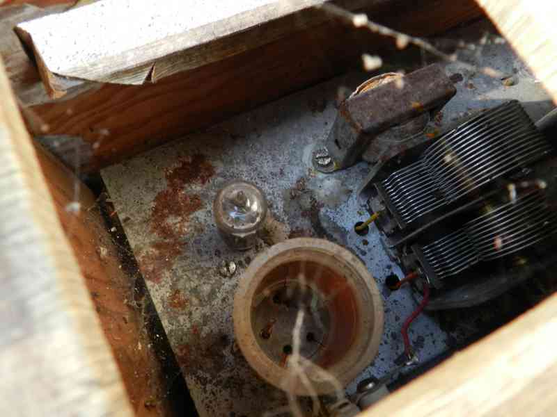
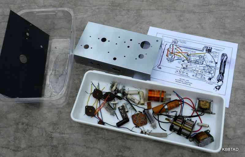
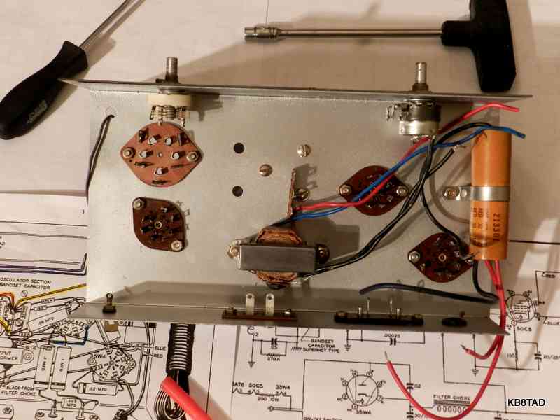
With all components removed, I went to work on the rusted chassis, sanding all exposed areas. After extensive sanding, just the discolored stains were visible. I decided to spray the chassis with a light coating of primer and metallic paint. That made a major difference in its appearance. I had carefully documented the wire color code on a pictorial copy before de-kitting. It turns out that the hook-up wire color code was based on its length. Apparently, Knight-kit had supplied precut and stripped hookup wire. Red was 2 inches long, orange 3 inches, yellow 4, blue 6, and violet 7 inches. I cleaned the tube socket corrosion with deoxit and used a small sewing needle with knotted thread on the pin openings. The needle and thread passed through the openings easily but the knots had enough width to thoroughly clean the openings after the deoxit treatment. The power switch/ regeneration control was also rescued with an overnight deoxit treatment.
Re-kitting the Ocean Hopper
The original electrolytic was in excellent physical shape but useless electrically. I decide to mount it back onto the chassis but remove its leads. In its place, I used 3 small individual electrolytics. A handy 100 MFD cap was used for the second half of the high voltage filter but the input filter was replaced at its original value so as not to stress the 35W4 rectifier.
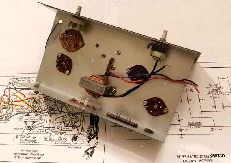
I replaced all of the rusted screws and nuts with new 6-32 hardware.
Re-building the kit after all the parts had been cleaned and tested or replaced was as much fun as the kit building experiences of the past. I cleaned the tube pins and the coil pins with a brass-bristle brush and a bit of deoxit.
Modifications for safety
Since the set is AC-DC with the power switch directly connecting one side of the power line to the floating B-, I decided on some safety improvements. There was not enough room on the chassis for a proper isolation transformer. Instead, the power cord was replaced with a two-button ALCI cord (Appliance Leakage Circuit Interrupter) recycled from a hair dryer. The ALCI plug was polarized. Therefore I wired the wide-blade neutral directly to B- and rewired the power switch to control the hot side of the power line, adding a new wire from the switch to the 35W4.
Ocean Hopper rebuilt. The clip lead is for testing a single inductive loop for a coax antenna
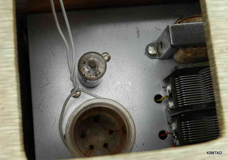
After rebuilding and testing, the set was working but intermittent. I traced the problem to poor contact between the coil pins and the coil socket. I solved the problem by crimping the socket connectors somewhat. Apparently this is a common problem with Ocean Hoppers. The cabinet repairs took considerable time and effort.
Another minor gotcha
The 0.1 MFD caps on the headphone feed can build up an electrostatic charge since each is connected to B+. Headphone tips are usually exposed and some headphones have exposed connections on the ear pieces also. I suggest connecting 1 megohm or similar resistors from the headphone tip jacks to chassis to drain the charge and avoid the "gotcha" if you use headphones with the typical uninsulated tips.
I used an external speaker but modern low impedance headphones can also be safely connected to the speaker terminals. For sensitive headphones, adding a resistive attenuator will limit hum. Place a 4 to 10 ohm resistor across the speaker terminals and a 100 ohm or so resistor in series with one of the headphone connections. Experiment with different resistor values as needed.
Alignment?
One of the advantages of these simple regenerative sets is they have no alignment needs.
Simple modification for low-impedance coax-fed antenna.
My antenna, like most ham radio antennas, is a low impedance antenna with a grounded coax connector. The Ocean Hopper is designed for a long wire antenna with no ground attachment because a ground is not recommended with an AC-DC radio. A simple work-around that is a major improvement in sensitivity for the Ocean Hopper is to use a simple one-turn loop of hookup wire around the plug-in coil and connect that wire loop to the coax antenna. The simple loop of wire is used in place of the set's fahnestock-clip antenna input. Note that this method makes no direct connection of any kind to the Ocean Hopper.
That squeal
The Ocean Hopper, as a regenerative set, can feed a signal back to the antenna. Regenerative sets were called "bloopers" in the early days of radio because of the ability to transmit especially at high levels of regeneration. Be aware of this "feature" when using it on the ham bands with a good antenna. This is less of an issue when listening to shortwave broadcasts or the AM broadcast band.
Playing with it
Listening to short wave with a minimalist regenerative set is a fun experience that introduced many to the wonders of radio. That may be the continuing appeal of this little set. Experience and a skilled hand are required to bring out its full capabilities, but that was and is part of the fun.
Knight-kit Ocean Hopper, Span Master and Space Spanner at reunion looking over the 1959 family album 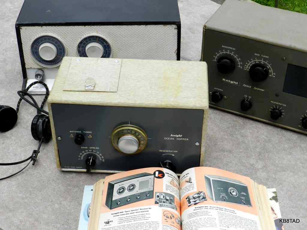
Schematics and further information
Click here for the
Knight-kit Ocean Hopper schematics from BAMA.
An alternate site for a pdf of the schematic and chassis pictorial is this link from K7JRL.
This link is to an article in the July 2010 Antique Wireless Association Journal
Here is the 1941 Hopper schematic.
Date 4-18-12
The Hallicrafters SX-71 receiver was the previous item on the bench.