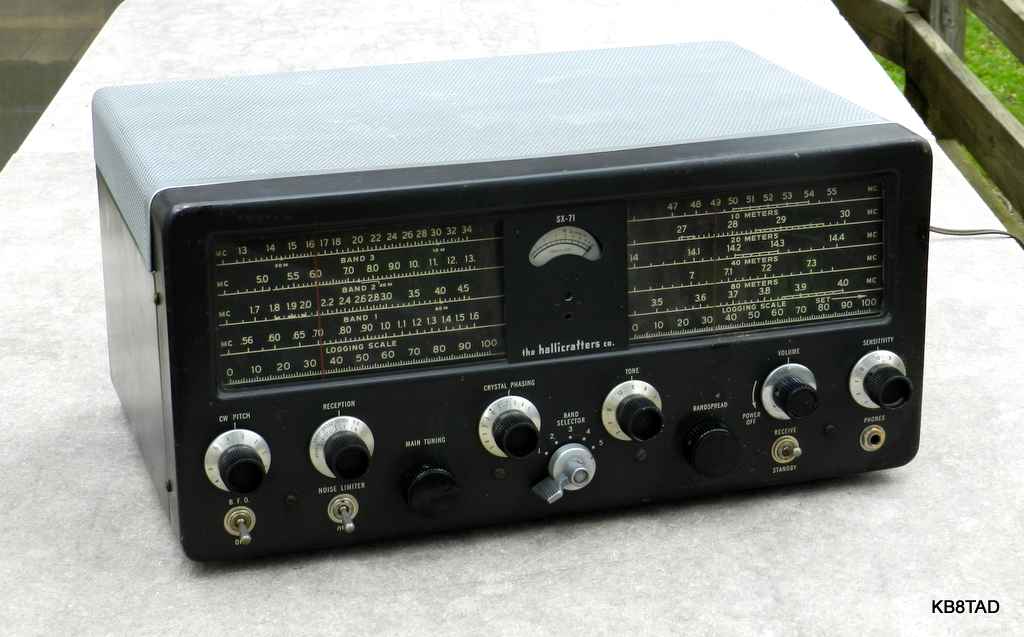
The SX-71 is a 5 band communications receiver covering AM broadcast and shortwave from 538 KHz to 34 MHz in four overlapping bands. A fifth band covers 46 to 56 MHz directly on the bandspread dial which is also calibrated for the 80, 40, 20, and 10 meter ham bands. A later version, Run 4, also has calibrated bandspread for the 15 meter ham band. The left slide-rule dial is the main tuning dial and the right slide rule dial is for bandspread and the 6 meter band.
The earliest SX-71 from 1949 has its dials in white with black markings. .
The following year, Hallicrafters changed the SX-71 dial to black with white markings. Bands 1 and 2 (538 KHz to 4.5 MHz) are single conversion. Bands 3, 4, and 5 are dual conversion. IFs are 455 KHz and 2.075 MHz. Like all Hallicrafters receivers with an "X" in the model number, the SX-71 has a crystal filter. The 455 KHz figure is nominal. The IF is aligned at the actual crystal frequency. A voltage regulator is used for the critical oscillator voltage.

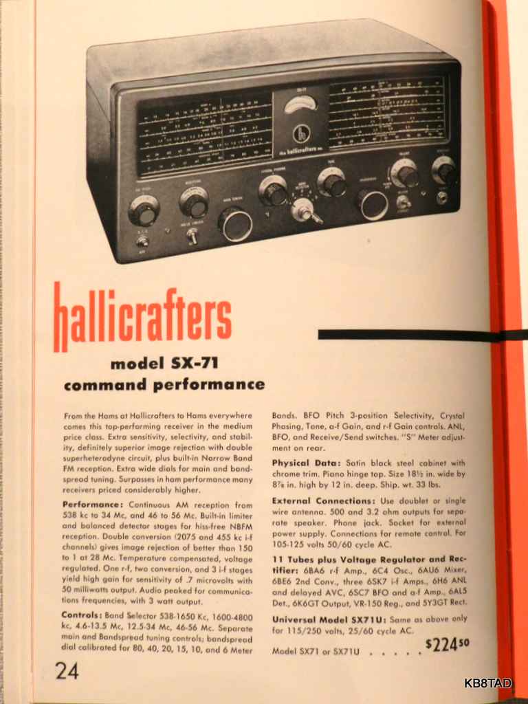
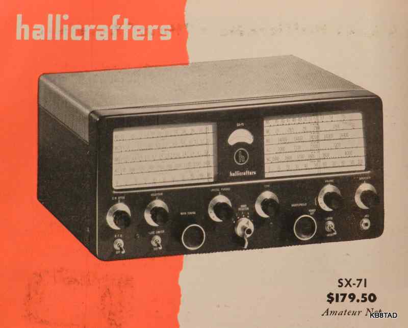
Introductory price of the SX-71 in 1949 was $179.50. The price rose to $199.50 in the January 1952 Newark ad and $224.50 in the Henry radio ad in December 1952, and $249.50 in the 1954 ARRL Handbook. Like most higher-end communications receivers, the SX-71 uses an external speaker. The matching speaker for the early white-face SX-71 is the R-44B. The matching speaker for the black-face SX-71 is the R-46.
Repairs
This SX-71, likely a Run 3, was in only fair cosmetic condition as purchased. The cabinet was in need of paint. The two tuning knobs and the volume control knob were missing. I substituted similar knobs as shown in the picture above but will be on the lookout for the exact knobs as well as the removable metal push-on "H" symbol which normally covers the S-meter zero adjustment. The bandswitch shield was missing, but a replacement was found.
A preliminary resistance check showed substantial leakage from chassis to the power line. That was traced to a leaky line-to-chassis micamold cap. I replaced it with a proper cap rated for line voltage applications. The screen grid caps and most other caps in the set were ceramic and in good shape. Many of the tubular caps in the main IF section (the opposite side of the chassis from the power supply side) are in low impedance cathode bypass circuits. None needed replacement. I replaced all tubular caps that see high voltage including the cap at the voltage regulator tube, the cap at the high voltage switch for BFO, and the 0.25 MFD cap for the B+ feed to the 6SH7.
As usual, I used a bit of contact cleaner sparingly on the controls and the tube pins and sockets. The toggle switches were all open. The switches were successfully repaired by applying Deoxit at the bat handles while the chassis was on its back, switches pointing up, letting gravity help.
I connected a speaker and tested the unpowered set with an ohmmeter between B+ and the plate connection of the output tube. That check tells me whether the output transformer and speaker connections are good. In this case, the expected scratchy noise did not happen. Something was wrong. Was it a bad output transformer? I found a broken connection between the accessory socket ground lug and the speaker ground terminal. Soldering that connection solved the problem. I then powered up the set slowly while monitoring current draw and B+ voltage. The electrolytic reformed properly, and I heard some AM broadcast noise. Band 1 and 2 worked to some extent. The BFO was not working and Bands 3 to 5 were almost silent.
The biggest problem turned out to be poor overall alignment with serious misalignment of the second IF (2075 KHz) making Bands 3 through 5 nearly deaf. Someone had apparently gotten in there with a "golden screwdriver", (ham-radio-speak for attempted alignment without the proper tools or knowledge).
Performance
After completing repairs and a careful alignment including the BFO, I was very pleased with the final performance. I listened to various 20 meter SSB conversations. Tuning was very stable after warm-up. The dual conversion design helps greatly with image rejection on the upper bands. The 6 meter dial markings on the bandspread scale were also very accurate after alignment. I listened to the local 6 meter AM ham radio net on 50.4 MHz. The SX-71 received it well, although, obviously not at the sensitivity level of transceivers such as the Gonset Communicator 4 previously on the bench.
For narrow-band FM, I aligned the ratio detector by clipping in a temporary circuit as shown in the alignment instructions using two selected 100K ohm resistors closely matched in resistance based on actual measurement. I used a 10 megohm digital meter in place of a VTVM since accurate small voltages can be read as either plus or minus on a digital meter. The Run 4 manual notes the use of a pair of 1 megohm resistors in place of the pair of 100K ohm. The actual value of those resistors is not that important, but the two provide a virtual center tap on the ratio detector and must be closely matched to obtain the proper zero voltage alignment point.
Manuals
Manuals, including a Sams Photofact,
can be found on BAMA although the scan quality is relatively poor. The Sams schematic shows the two 100K ohm resistors needed for FM alignment in dotted lines, but does not mention the need for a temporary lash-up of those resistors.
Here is a December 1950 Hallicrafters service bulletin from w9wze.org available via the web archive.
Here is an excellent PDF copy of the SX-71 Run 4 manual from Julian Bunn.
Here
is Julian's SX-71 page with more information and some very nice pictures.
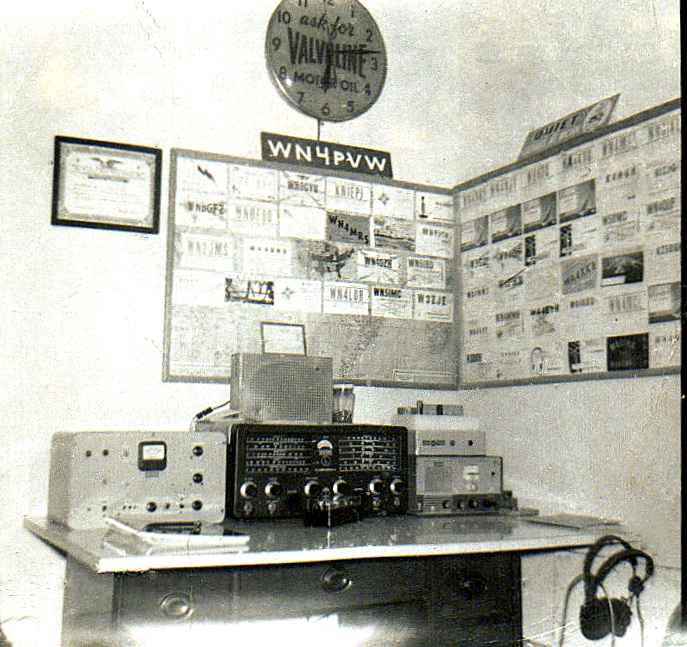
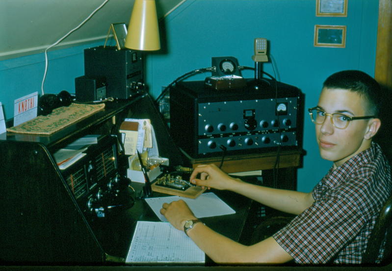
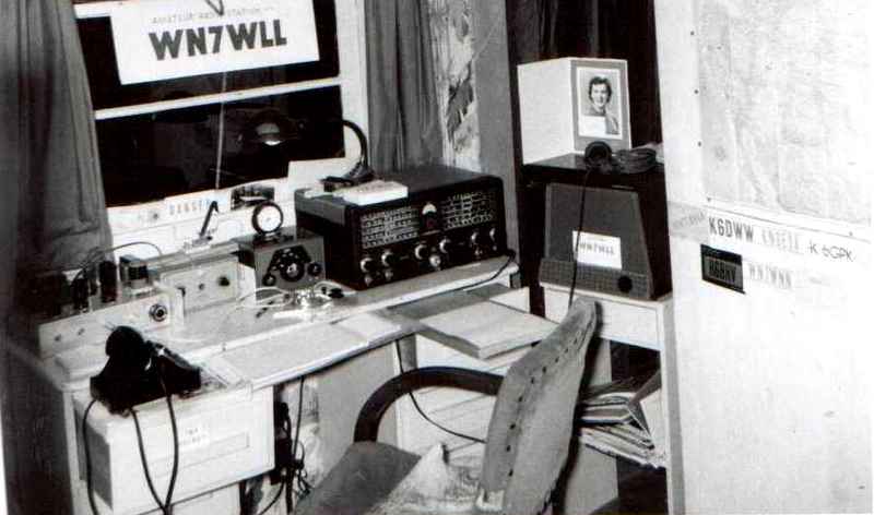
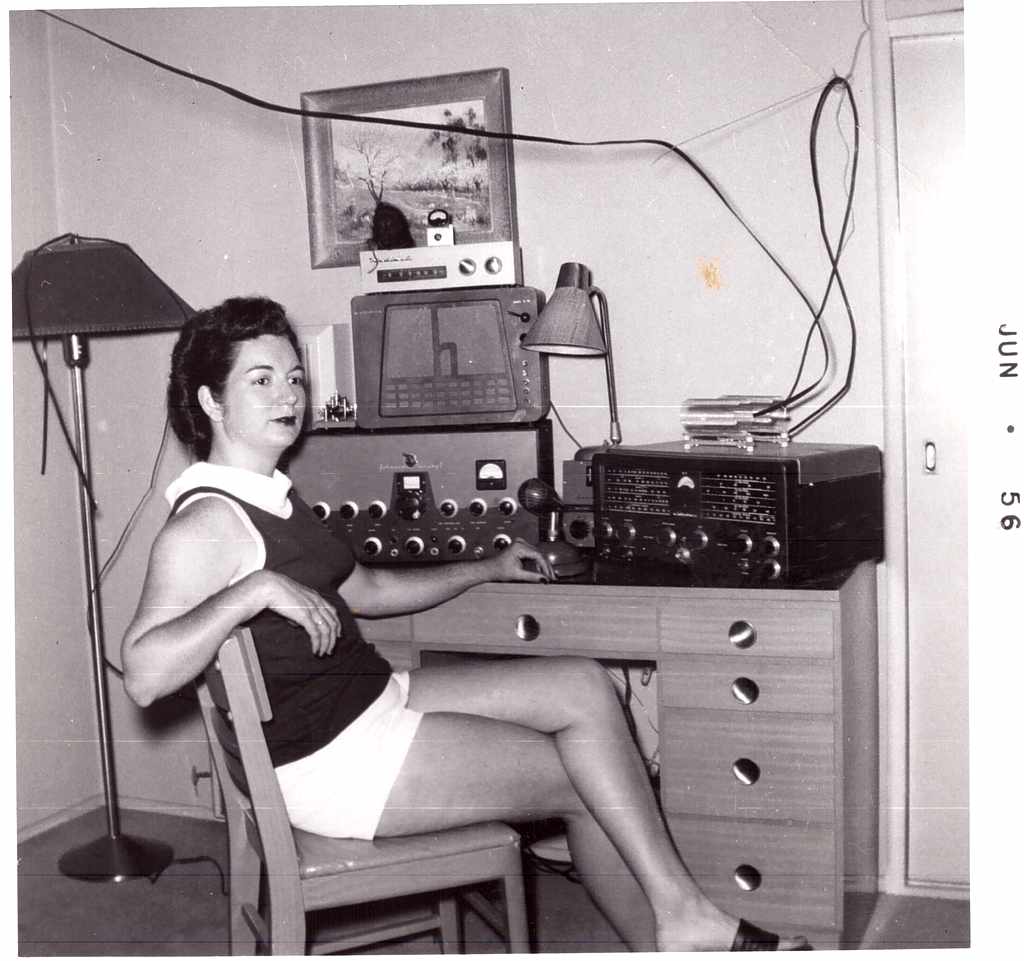
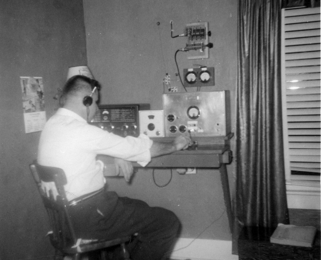
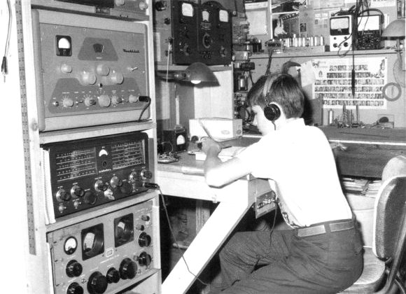
SX-71 in vintage hamshacks
Here is a picture of the SX-71 in K5LN's novice hamshack. See
more of K5LN's various shack pictures over the years at QRZ.
date: 4-8-12, 12-22-13, 8-12-15, 3-8-19, 8-5-19
A Gonset Communicator IV 6 meter transceiver was the previous item on the bench.