Problem 3.2 - The Sunpower EG-1000
Stirling Engine/Generator
Since 1974 Sunpower,
Inc has developed Free Piston Stirling
Engine/Generators ranging in power levels from 35We
to 7.5kWe.
This exercise concerns the ideal performance of the EG-1000 Stirling
engine which is gas fired and was designed to generate electricity
(1kWe) as well as
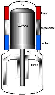
to provide hot water for a private home. This engine is shown in the
figure below together with a simplified schematic diagram. Notice
that there are two pistons - a power piston which allows compression
and expansion of the working gas (helium) and a displacer piston
which shuttles the working gas between the hot expansion space VE
and the cold compression space VC,
through the series connected heater, regenerator and cooler.
Conceptually the Stirling engine is the simplest of all heat engines.
The working gas is sealed within its cylinder by the power piston.
The displacer piston shuttles the gas such that the gas will compress
while it is mainly in the cool compression space and expand while in
the hot expansion space. Since the gas is at a higher temperature,
and therefore pressure, during its expansion than during its
compression, more power is produced during expansion than is
reabsorbed during compression, and this net excess power is the
useful output of the engine. Note that there are no valves or
intermittent combustion, which is the major source of noise in an
internal combustion engine. The same working gas is used over and
over again, making the Stirling engine a sealed, closed cycle system.
All that is added to the system is steady high temperature heat, and
all that is removed from the system is low temperature heat and
mechanical power.
|
|
The linear electrical generator (not shown in the
above schematic) is comprised of powerful rare-earth magnets in
the piston cutting a magnetic circuit and coils in the cylinder.
This produces 240 Volts at 50 Herz - designed for operation in
Europe, and is capable of producing more than one kilowatt of
electrical power output at an efficiency of around 90%.
Note:
The hot water is provided by operating the cooling water at a
temperature of 50°C.
|
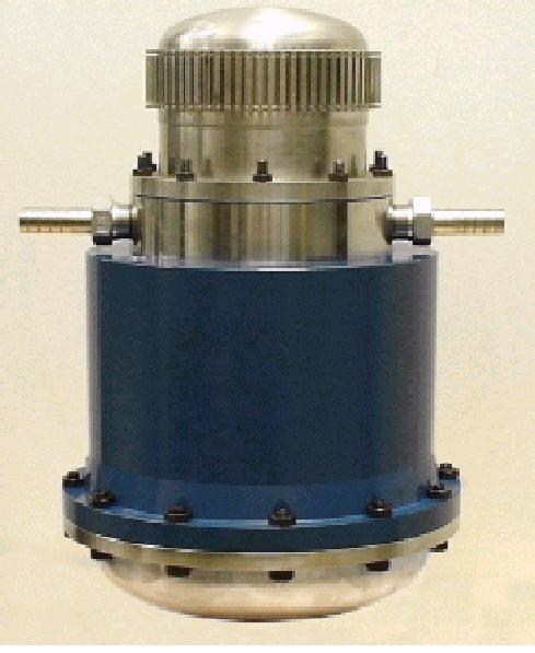
Figure 1 -
The Sunpower EG-1000 free-piston Stirling engine/generator
Note that since 1995 the
EG-1000 technology was used by British Gas to develop CHP (Combined
Heat and Power) units – the 1kW engine/generator is currently
manufactured by Microgen
Engine Corporation (refer
to their History
and Engine
web pages).
Unfortunately
the analysis of actual Stirling cycle machines is extremely complex
and requires sophisticated computer analysis, mainly due to the
non-steady convective heat transfer processes. We consider an
idealized model of this engine defined in terms of the P-V
diagram shown below, and will attempt to quantify the
performance characteristics from this ideal model. These are the
mechanical output power, the thermal efficiency, thermal power for
home water heating and the effect of the regenerator on the thermal
efficiency.
The working gas used is helium, which has the
advantage of having a low molecular weight and high thermal
conductivity compared to air, allowing a high efficiency system.
Process (1)-(2) is the isothermal compression of the helium at
temperature TC = 50°C, during which
heat QC is rejected to the cooling
water. Process (2)-(3) is the constant volume displacement process
during which heat QR is absorbed from
the regenerator matrix. Process (3)-(4) is the power producing
isothermal expansion process at temperature TE =
500°C, during which heat QE is
absorbed from the gas burner, and finally process (4)-(1) is the
constant volume displacement process during which heat QR
is lost to the regenerator matrix. Thus the ideal
Stirling cycle consists of four distinct processes, each one of which
can be separately analysed in accordance with the methods that are
described in Chapter
3b. State (1) is defined at a maximum
volume of 650 cu.cm and a pressure of 10 bar, and State (2) is
defined at a minimum volume of 550 cu.cm. This large minimum volume
is the dead space due to the unswept volumes including the heater,
regenerator and cooler spaces. (Note
that the values presented here are not actual values of the EG-1000,
however were devised by your instructor for purposes of this exercise
only).
Figure
2. The ideal Stirling cycle engine P-V
diagram
Since the Stirling cycle is a closed cycle, we can
consider each process separately. Thus the work done for each process
can be determined by integration. This is equivalent to evaluating
the area under the P-v curve, as follows:
The working fluid is helium which is an ideal gas, we
use the ideal gas equation of state throughout. Thus P V = m R T,
where R = 2.077 kJ/kg K, and
 = CV
= CV
 ,
where CV = 3.116 kJ/kg K. (refer:
Ideal
Gas Properties)
,
where CV = 3.116 kJ/kg K. (refer:
Ideal
Gas Properties)
a) From the given conditions at state 1 (P = 10
bar = 1000 kPa, V = 650 cc, T = 50°C) determine the mass of working
gas (helium) used in the cycle. [m
= 0.00097 kg (close to 1 gm)]
b) Determine the net work done per cycle
(kiloJoules): WE + WC
(Note that the compression work WC
is always negative). At a frequency of 50 Herz (cycles
per second) determine the power output produced by the engine. [Wnet
= 0.151 kJ/cycle, Power =
7.55 kW]
c) Determine the heat absorbed in the expansion
space QE during the expansion process
(3)-(4). [QE
= 0.260 kJ]
d) Evaluate the Thermal Efficiency
 th,
defined as:
th
= (WE + WC)
/ QE. (Net mechanical work done
divided by the heat supplied externally by the gas burner). [58
%]
th,
defined as:
th
= (WE + WC)
/ QE. (Net mechanical work done
divided by the heat supplied externally by the gas burner). [58
%]
e) Determine the amount of thermal power
rejected to the cooling water. Note that at a temperature of 50°C
this is suitable for providing hot water for the home, as well as
providing home space heating capability. [QC
= -0.109 kJ/cycle, Thermal
power to cooling water = 5.45 kW]
f) Determine the amount of heat transferred to
the working fluid QR as it passes
through the regenerator during process (2)-(3). [1.36
kJ] If this heat were to be supplied
externally by the gas burner, (i.e. no regenerator) what would be
the new value of thermal efficiency
th?
[9.3%]
|
|
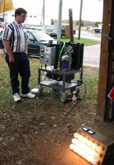
In this photograph we see the Sunpower
EG-1000 being demonstrated using sawdust pellets as the fuel, and
generating more than 1000W of electricity to a light panel. This
was done at the Sustainability Fair in the Fairgrounds of Athens
Ohio, 2001. A closeup
photograph of the basic system is
shown. Notice the closed cycle radiator and vibration pump used in
the water cooling system.
|
______________________________________________________________________________________