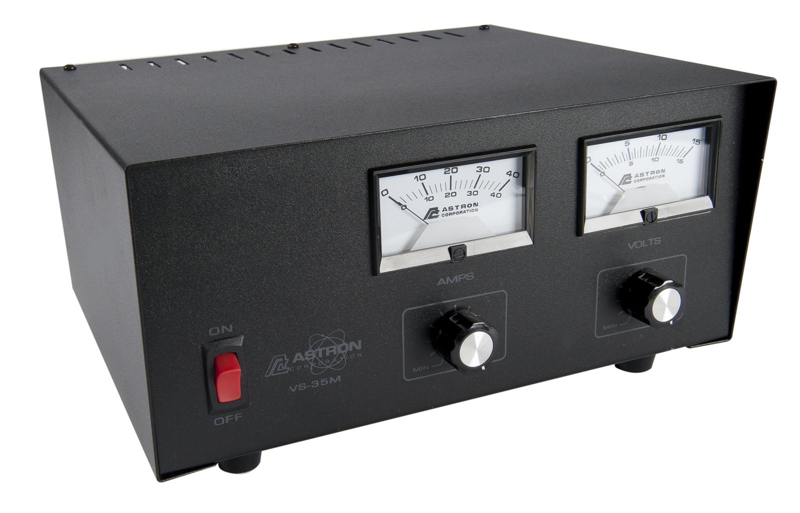
Since covering a pair of Pyramid power supplies, I have been asked about Astron. Here is one of my favorite Astron power supplies because of the variable voltage and variable current limiting. According to Astron, it is capable of 25 amps continuous and 35 amps intermittent at a 50% duty cycle. That current handling is true only at the rated full 14 volts output like its fixed-voltage brothers the RS-35 and the RS-35M ("M" stands for meters) with which it shares nearly all of its circuitry and components. At lesser voltages, the current must be de-rated since the pass transistors must take up any excess voltage at a given current. At 10 volts, the supply is rated at 15 amps continuous and at 5 volts the rating is reduced to 7 amps.
Like the Pyramids and all such linear power supplies, this one is heavy with the large transformer inside. It has both an ammeter and a voltmeter. Controls on the front panel are potentiometers that allow adjustment for variable voltage and current limiting.
Astron schematics
There are plenty of schematics on the web for Astron linear supplies with most available from the excellent repeater-builder site. which is loaded with information on Astron power supplies.
Nearly all of the Astron schematics and circuit boards are very similar if not identical. The resistor marked Rx or R3x in parallel with R3 sets the maximum current allowed before fold-back current limiting and is unique to each model depending upon the actual maximum current handling capabilities of the model.
Here is an annotated schematic of the Astron RS-35M detailing the workings of the various parts of the Astron circuit. The annotations were originally written in the December 2005 QST magazine, in an article called "Hands-on Radio, Experiment #35".
Here is an original Astron owner's manual for the RS-50M and others in the "50" series. In comparing to the 35 amp series such as RS-35M, the main schematic difference is that the RS-50M has more pass transistors and a different hand-selected resistor (R3x) across R3 to detect maximum current allowed before fold-back. The fold-back current is obviously different for a 50 amp Astron versus a 35 amp. (But notice the typo wich mentions "8" pass transistors and also "four" transistors in the same paragraph in 2.2. It appears that Astron might simply have copied the manual from a 35 amp version and changed the numbers but forgot to change the "four".)
A dead Astron bargain
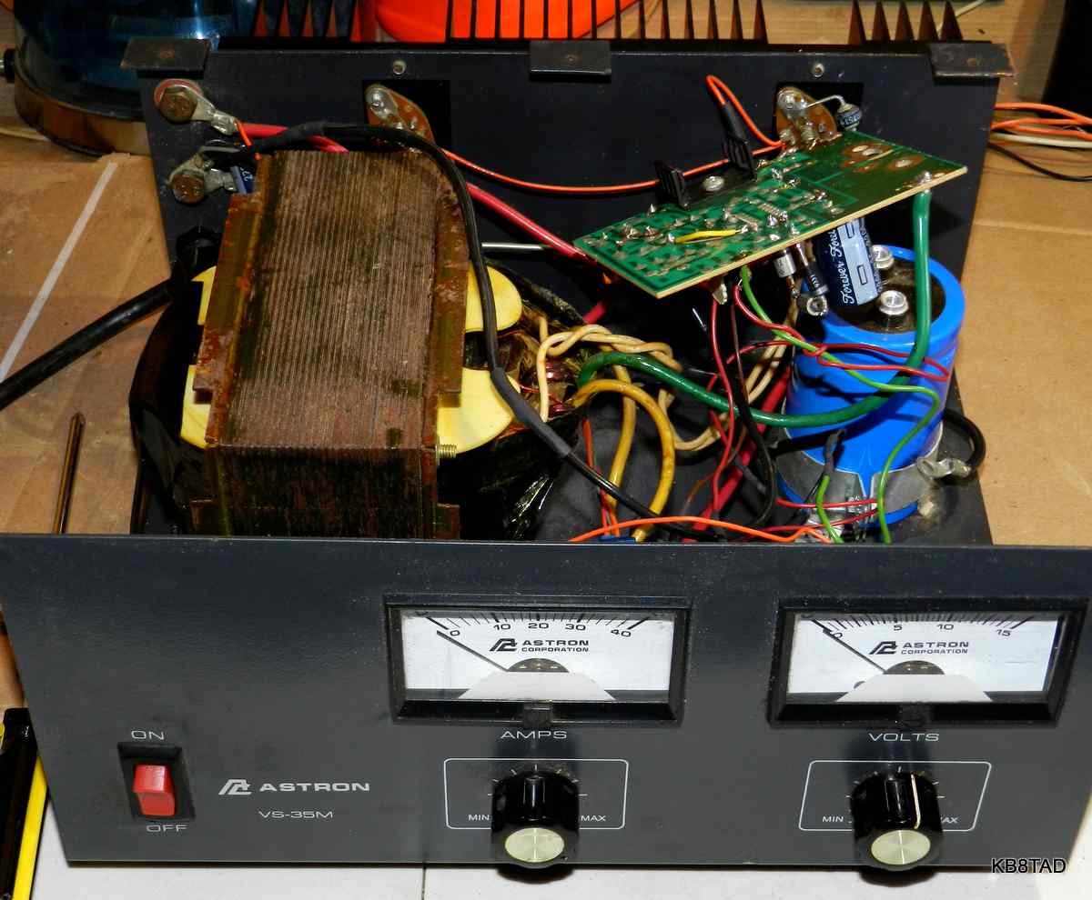
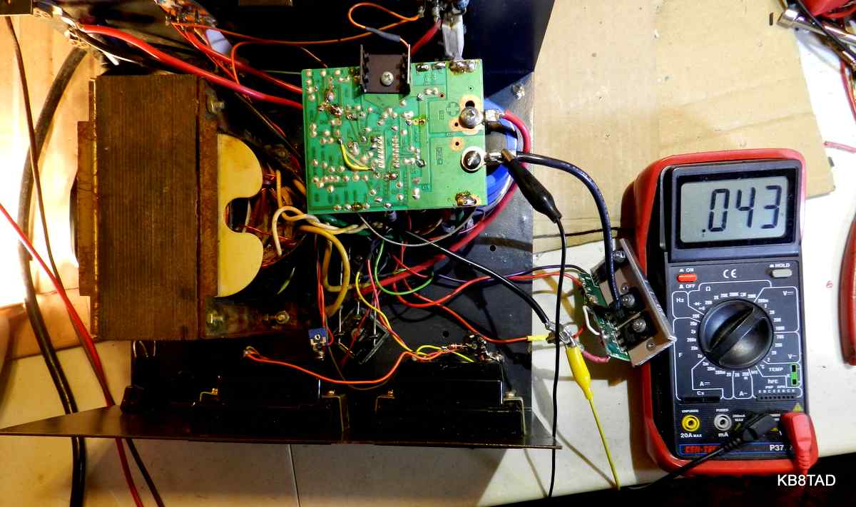
I bought this piece at a hamfest. It was dead so the price was right. Inside I found a blown fuse, an open diode, a burned-out SCR, a blackened 43 ohm resistor, a near-shorted TVS, four leaky or shorted pass transistors, a disconnected voltmeter, an LM-723 regulator chip that was probably dead and two traces on the circuit board that had evaporated. The small 20K ohm variable resistor for adjusting the voltmeter was missing with the wire left hanging, evidence of an attempted repair. But hey, what do you want for $10? At that price, it was a bargain even for just the transformer, case, and meters. I wanted a variable supply and figured as a worst case I could always replace the active components with an LM-317 and new pass transistors. I had at an earlier hamfest bought a large heat sink which came with a set of the same 2N3771 pass transistors as the ones used by Astron, all of which had tested good. Nearly all linear Astrons use the same circuitry, differing mainly in the number of pass transistors.
This was not my first Astron repair, so I quickly replaced the fuse, pass transistors, the diode, the resistor, the 39 volt P6KE39A TVS, and two jumpers for the missing circuit board traces. I had plenty of hefty 15 volt zeners in the junk box and added a 9 volt to two of those to make up a quick replacement for the 39 volt unidirectional transient voltage suppressor (TVS). The three zeners were used because I already had them. That TVS or zener protects the LM-723 voltage regulator chip from over-voltage spikes. The LM-723 has a maximum input voltage of 40. I checked the three zeners to make sure they would strongly clamp at 39 volts. As it turned out, the LM-723 proved to be in good shape. Normally that chip is the first casualty in any Astron failure. I suspect it may have been replaced in an attempt to repair the Astron.
I was not sure about the SCR crowbar as it was obvious that without a heatsink a replacement did not have enough current handling capability in the event of a shorted pass transistor. I removed the burned out one and did not replace it for the time being since I just wanted a high current variable bench supply and could keep an eye on the voltage.
My guess at the cause of failure was likely a nearby lightning strike that may have followed an antenna or ground into a radio shack. I doubted that the spike had come from the power line since the factory-installed MOV across the transformer primary was intact.
Checking out the circuit.
As noted, the heart of this power supply like all Astron linear power supplies is the little LM-723 regulator. The one in the Astrons is socketed, allowing easy replacement of this very inexpensive 14 pin chip.
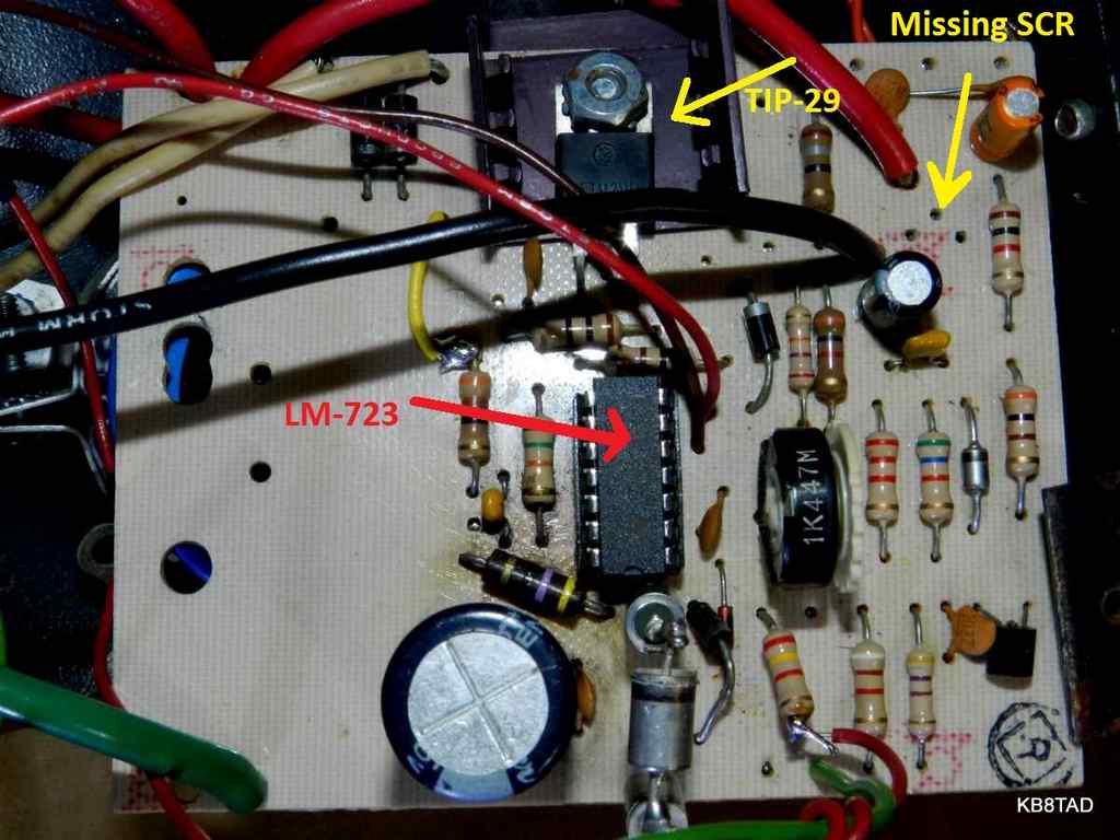
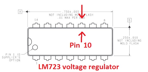
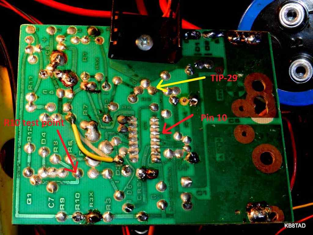
The LM-723 is a complete voltage regulator all by itself. Its voltage output (pin reference 10) provides a maximum current of 150 mA which is then fed to the base of a TIP29 NPN transistor with a small heatsink mounted directly on the circuit board. That TIP29 acts as a simple current amplifier. The voltage at its base determines the voltage at its emitter. The emitter of that TIP29 feeds the bases of four more 2N3771 NPN pass transistors which are wired in parallel. Those four pass transistors act as a bigger current amplifier. The voltage at the bases of the four pass transistors determines the voltage at the emitters which provide the output of the power supply. The collectors for all the 2N3771 transistors are fed by unregulated DC from the combination of the power transformer, a pair of heavy duty diode bridges and the large electrolytic capacitor on which the circuit board is bolted.
The Astron crowbar
The crowbar over-voltage protection circuit in Astron power supplies is an SCR that is activated by a small transistor with zener reference and resistor voltage-divider network. The crowbar SCR short circuits the output which then typically kicks in the current-limiting (fold-back) function of the LM-723 or possibly blows the fuse. The fuse must not be larger than the recommended size. A larger fuse will no longer provide full protection for the supply. While the SCR in this set had apparently failed quickly, I have repaired another Astron with a burned-out hole in the circuit board because the SCR heated up and destroyed itself trying to short out a power supply with very leaky transistors. The oversize fuse was still intact.
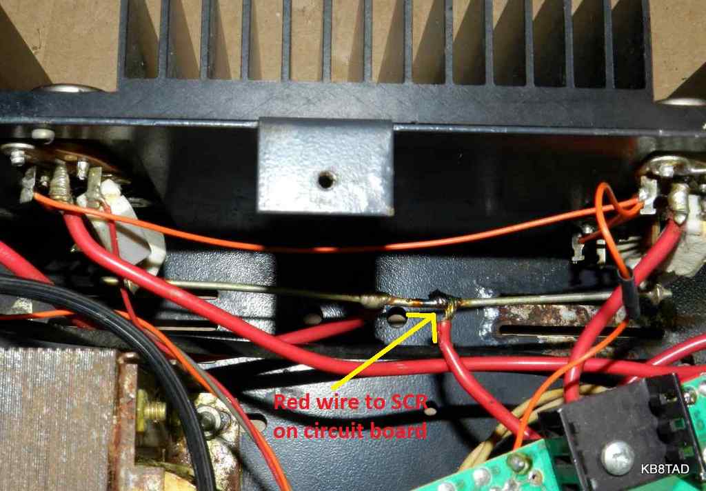
Unlike the Pyramid PS-25, the trigger point for the Astron SCR crowbar is not adjustable. The 5.6 volt zener and resistor divider of R8 (5.6K ohm) and R10 (9.1K ohm) turn on a transistor which triggers the gate of the SCR when the output voltage is about 16 volts. The SCR which is normally rated at about the maximum ampere capability of the power supply is wired directly across the output of the supply and conducts when triggered. The SCR can be checked by disconnecting its heavy red wire and placing a light-bulb load between it and the B+ terminal. I checked the values of the resistors in the transistor trigger circuit to verify that they were within tolerance. The two resistors add up to 14.7K ohm across the power output. At 14.7 volts with those resistors, the base voltage would be 5.6 matching the emitter voltage controlled by the zener. If the base voltage increases enough to overcome the PN junction drop, the circuit will trigger. Bridging resistor R10 with another resistor should increase the base voltage enough to turn on the transistor and test the crowbar. Since one side of R10 is circuit ground, a clip lead to ground and a resistor such as a 10K or 15K at the transistor base connection to R10 should be enough to trigger the SCR if the circuit is working.
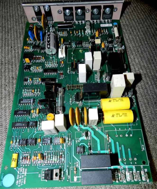
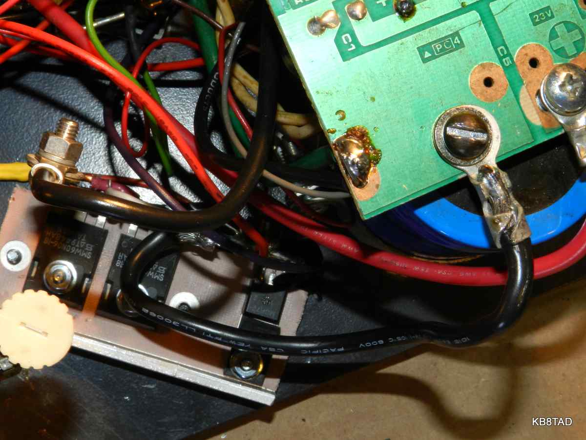
The Astron circuit board
One of the weaknesses of the Astron design is that the components are mounted upside down on the circuit board. That makes troubleshooting more difficult. However, the voltages can be checked with the circuit board still in place. The circuit board is held in place by the bolts on the large electrolytic capacitor. If the board is freed to get to the components, I recommend using a bit of contact cleaner on the little variable voltage adjustment pot. That pot is used to set the maximum operating voltage of the supply, typically 13.8 volts.
Troubleshooting an Astron
is similar to that described for the Pyramid supplies. If the fuse is blown and therefore no voltage output, check to see if the crowbar circuit was activated.
Assuming 20 volts or more at the collectors, measure the voltage at the output terminals of the power supply. If the voltage is too high (more than the design maximum of 14 volts) chances are that one or more of the pass transistors is shorted or leaky which caused the SCR crowbar to short out the supply and the fuse to blow. Check the pass transistors. If there is no voltage at the output terminals but 20 or more at the collectors, then check the bases of the pass transistors for voltage. If no volts there, check for voltage at the output pin 10 of the LM-723. That test point is easy to locate since the circuit board trace goes directly from pin 10 to the base connection of the TIP29. (see circuit board picture). If no volts there, replace the LM-723 chip. Note that we skipped checking the collector and emitter voltages of the the TIP29 on the circuit board since that transistor is the least likely to fail.
Troubleshooting an Astron with no voltage at the output but fuse not blown
I usually find the LM-723 chip dead when the supply fails with no output but with an intact fuse of the proper size. I check to see if the non-regulated portion of the supply is working as described above by measuring the voltage between the body of the pass transistors (connected to the collectors) and the negative output terminal. I also check for shorts at the output to see if the over-current (foldback) function of the LM-723 may have kicked in.
If the non-regulated portion of the supply is working and there are no shorts on the output, a quick voltage check at pin 10 will verify whether the chip is in fact functional. That voltage would normally be the intended output voltage plus any voltage drops (of the PN junction of the TIP29, the 2.4 ohm resistor and diode between the TIP29 emitter and the bases of the 2N3771 transistors, and the base to emitter PN junctions of the four 2N3771 pass transistors.) The schematic shows pin 10 voltage to be 14.8 at no load and 16.5 at full load.
Thoughts about crowbar protection.
The crowbar circuit in the Pyramid PS-25 previously on the bench used a TYN-690 SCR which was mounted in a heat sink on a separate board. The SCR on this Astron was directly mounted on the circuit board and had no heat sink. I consider that a major design weakness. Very old versions of an Astron had a stud-mounted SCR that used the case for a heat sink. Some other newer Astrons use mica insulators to mount both the SCR and the TIP-29 on the bottom of the case for a heat sink, a much better design. While an SCR without a heat sink might be fine for triggering the fold-back overload function of the 723 chip, the arrangement is inadequate for a hard short circuit in a pass transistor. Could there be a better way? I thought about using a heavier SCR on a real heat sink or the case bottom but then thought about the purpose of the circuit. It is there to prevent an unexpected over-voltage at the output.
Replacing the crowbar shorting circuit with shut-off over-voltage protection.
A lot of time has elapsed since the linear Astrons were first designed. During that time, the power MOSFET has become part of many inverter power supplies, especially the Uninterruptible Power Supplies (UPS) for computer applications. I had several such supplies which I acquired for free or cheaply because the large sealed lead-acid batteries cost nearly as much to replace as a new UPS on sale. I had re-purposed the UPS transformers as bucking, isolation, or power transformers. Each of the UPS used heavy-duty N-channel MOSFETS on the circuit boards which I had added to my "junque" box.
Astron MOSFET crowbar modification schematic
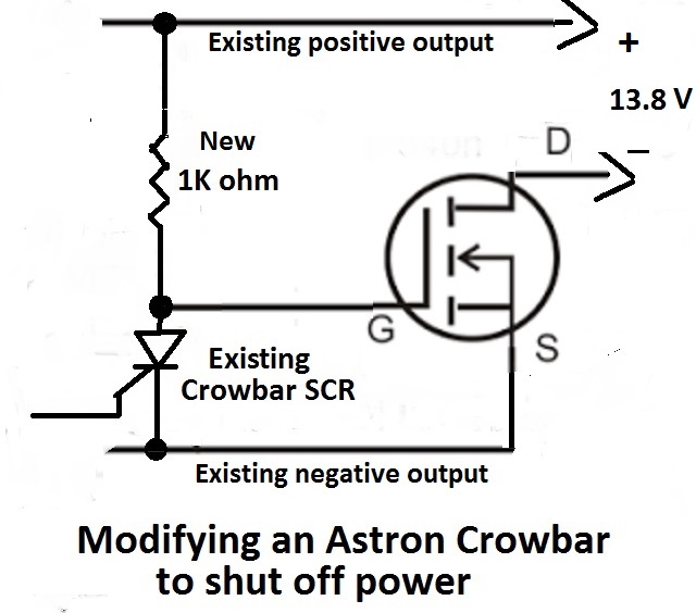
I checked the specs on the MOSFETS in the "junque" box by researching on-line datasheets, using the ones shown on the circuit board pictured above complete with heatsink and insulation. The heat sink had a transistor and a three-terminal regulator mounted on it. I removed those so I could mount an SCR to it. I decided to use just a pair of the MOSFETs and cut the heat sink and printed circuit board leaving just the connecting pads. The resulting MOSFET board was wired between the existing negative terminal at the electrolytic and the negative output lead. I moved a couple of existing Astron leads that were attached at the negative output terminal such as the meter feed to the main Astron circuit board to keep them out of the loop when shut down occurred. On testing the solution using a parallel pair of MOSFETS, I found that the very low Rds resistance cut the output voltage only slightly, about 0.14 volt when drawing 18 amperes.
Do we even need an SCR?
I see no reason why I could not use one of those 15 volt zeners in my "junque" box in series with a resistor to directly control the gate of a MOSFET. If I wanted a bit more than 15 volts before shut down, then a diode in series would likely do the trick. I will do further experiments and may test such a solution in a high current
home-brew power supply. Let me know what experiments you have tried. A small capacitor such as a 0.01 ceramic cap might be added between the source and gate terminals if I find that is needed in a high RF environment. For now, I will leave the Astron as modified.
One of the issues with using the MOSFET in a variable supply is that the lower limit of the supply is about 3.5 volts. That is not a problem for my uses of the supply. For a standard RS-35 or RS-35M with fixed voltage output, that would also not be a problem. About the only differences between the RS-35M and the VS-35M is the addition of the voltage and current limit controls as shown on the schematics. Nearly all else is the same.
Dealing with the slight voltage drop
You can reduce the slight voltage drop by using more N-channel MOSFETS in parallel. I have been asked whether a similar circuit could be designed that avoids the slight voltage drop incurred by inserting N-Channel MOSFETS. Yes, but that would require including the output rail in the feedback loop. That is best handled by using P-Channel MOSFETS (obviously in the positive lead). I used N-Channel MOSFETS because they were cheap (free from a recycled UPS chassis). If you build a circuit with P-Channel MOSFETS, let us know the results and share the circuitry.
date: 6-15-15, updated 6-27-15, 8-9-20
Testing and modifying a Robinair Volt-Wattmeter for a lower range was the previous project "on the bench".