An early spectrum display
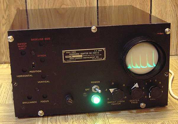
The U.S. Army Signal Corps BC-1031 series of panoramic adapters were used by Allied forces during World War II and later. It is an early form of spectrum analyzer. The BC-1031 displays radio signals in a spectrum of up to 100 KHz higher and 100 KHz lower than the signal tuned in on a companion receiver. Practically any single conversion superhet with a 455 KHz IF can be used as companion receiver. This BC-1031-C is serial number 68, made by the New London Instrument Company. The BC-1031A and B and the Panoramascope are nearly identical instruments, all centered at 455 KHz. All were designed by and based on patents held by Panoramic Radio Corporation. The Navy RBU is a very similar unit for the preferred Navy IF frequency of 400 KHz and a sweep of 25 KHz plus and minus, also made by Panoramic Radio.
Connection to companion receiver
The BC-1031 connects to a receiver's converter plate through a 50,000 ohm resistor and coax cable. The manual recommends drilling a 3/4 inch hole in the receiver and installing a matching coax connector or using a grommet to route the coax. If you find such a hole in a military receiver, look for the 50K ohm resistor to the converter plate. The added hole may be an authentic military modification.
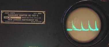
The panoramic display is adjusted so that the signal being listened on the companion receiver is at the center of the display. Signals in the range of 100KHz plus or minus the tuned signal frequency show up as pips of varying shape to the left and right of center. Pip shapes vary with the type of transmission. The height of each pip varies with signal strength. An AM signal shows up as a pip that has variations in height caused by the modulation. The manual for the BC-1031 shows how to identify several types of signals such as SSB or FM by their pip displays.
Repairs
Besides the missing graticule, this unit came without tubes, fuse and holder, and with one of the shielded cans lying loose inside the case. I was able to find replacement octal tubes relatively quickly, but locating a 3BP1 cathode ray tube (CRT) took some time. The schematic is printed on the bottom chassis cover. The shielded coil lying loose inside was part number Z-101-01, the 681 KHz oscillator coil with in-line RF choke for the reactance tube. It was missing its 6 mica capacitors and 4 resistors, all of which are part of the module inside the shield. Both the oscillator coil and the RF choke were intact although their thin wires had been disconnected, apparently when the caps and resistors had been removed. I checked both coils on my Sencore Z meter to determine inductance and rule out any shorted turns. I removed what appeared to be a substitute modified coil apparently to replace the Z-101-01. The substitution appeared to be half of an IF coil with its shield can cut in half. It had been partially wired in but the modification was not completed.
I decided to rebuild the Z-101-01 since it appears to be the heart of the system, essentially a 681 KHz oscillator that is swept plus and minus 100 KHz 30 times per second by the reactance tube as triggered by a blocking tube oscillator. Six dipped micas and 4 resistors later, the coil module was rebuilt. I rewired it into place per the schematic after taking some notes on the modifications found, (in case I had to retreat).
Shorted power transformer
After rewiring the Z-101-01, I did some power supply tests with the rectifiers removed and the CRT not yet in place. The power transformer drew nearly one amp with my isolated variac at barely 40 volts input. I removed all the secondary wiring. Same problem. Measurements indicated that the highest voltage winding was apparently shorted.
The power transformer in an oscilloscope or a CRT display such as a Panoramic adapter typically has a very high voltage low-current winding for the negative DC feed to the cathode of the CRT. It also has a separate 6 volt filament winding for the CRT which must withstand that high negative voltage bias to avoid heater to cathode breakdown. The only scope transformer I had on hand did not have sufficient current capability (55 milliamperes needed) for the main B+ high voltage.
Adapting a substitute
I found a potted power transformer of similar size and mounting as the original in the "boxe de junque", but it did not have either of the special windings. It had plenty of current rating for B+, about twice the need, and it stated "1500 VRMS test". Since the BC-1031 uses a 6X5 rectifier, I decided to use the transformer's 5 volt rectifier winding for the CRT filament. Because that winding was capable of 3 amps and the CRT would only need 0.6 amp, the actual voltage would be a bit higher than 5, about 5.4 volts. I also used one side of the transformer's high voltage winding to feed a solid state half-wave doubler circuit consisting of a new capacitor and 1N4007 diodes, re-using the original high voltage caps for the second side of the doubler. I left space on a new terminal strip in case I had to triple the voltage. A 10K resistor was placed between the transformer winding and the new cap to limit current in case of a short circuit. I did not want to risk the replacement power transformer. The doubler measured only about -640 volts. I thought of going to a tripler circuit, but testing with the 3BP1 in place showed a trace that was nicely focused and of decent brightness, despite the lower filament and high voltage. The existing 2X2 rectifier and socket were left in place for cosmetics but no longer connected.
Alignment
As expected, major alignment was needed. I followed the manual closely. The second pair of IFs are peaked at 226 KHz as in a normal radio. However, the first pair of IF transformers are stagger-tuned with the primaries at 345 KHz and the secondaries at 545 KHz. This assures the broadband response needed for the spectrum sweep. The extremes of the sweep are amplified more than the center since the companion receiver would normally provide greater amplification at the center (455 KHz) of the spectrum.
Other mods
The military twist-lock AC input connector had been replaced by a standard two blade power connector. I replaced it with a modern IEC computer-style three prong connector. I left another modification in place. That was an added shielded cable from the detector tube to a phone jack mounted in an existing center hole on the rear panel. The mod allows audio or other external monitoring of the spectrum, a useful feature. The front panel thumb screws were missing. I substituted rack-mount screws.
Power line filter
The power line filter caps are large enough to pop a GFCI. I am hesitant to modify this to a lesser cap however since filtering might be compromised The trace is flat when there is no input to the SO-239 jack. For now, the 3-wire grounded AC cord is sufficient protection.
"Playing" with it
After repairs and alignment, I found the BC-1031C a fun instrument to use and play with. The signals in the spectrum display move in step as the companion receiver is tuned across the band. With a short piece of unshielded wire for signal pickup, it actually sniffed out a local noise source as shown in these pictures, likely from a switching power supply and its harmonics. The Signal Corps manual indicates that as a possibility. In a normal spectrum display, a direct noise source would appear as a stationary signal, not moving with the rest of the displayed signals when the companion receiver is retuned. Using coax in place of the unshielded wire returned the trace to flat-line.
See also the Panoramic Radio Company Panadaptor model PCA-2 T-200 that I repaired some time ago. It is a smaller postwar commercial display that performs the same function as the BC-1031.
More info on Panadaptors
For lots more info on Panadaptors and the Panoramic Radio Corporation, see the excellent writeup by Chuck McGregor N7RHU .
BAMA has the manual in PDF form under its "miltest" section.
The RME-45B receiver was the previous item on the bench.