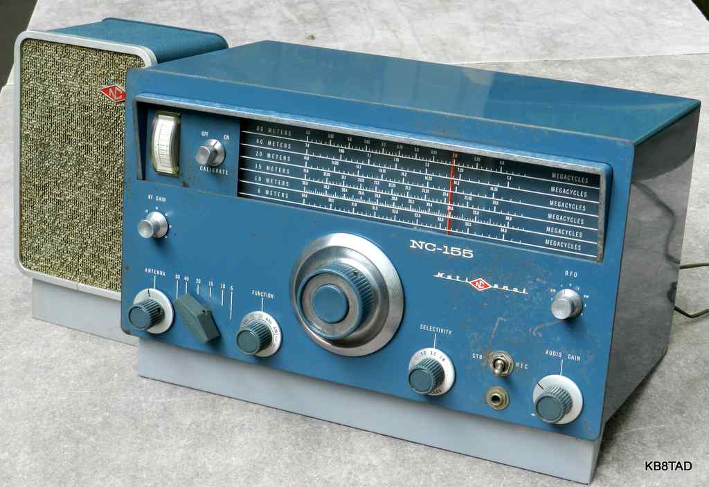
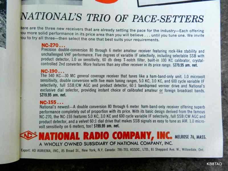
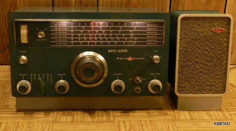
The National NC-155 is a ham-bands-only receiver covering the 80, 40, 20, 15, 10 and 6 meter bands. Has BFO, product detector, three levels of selectivity (5, 3 and 0.6 KHz) and separate RF gain and volume controls. It is a somewhat cost-reduced version of the NC-270, leaving out the crystal calibrator and notch filter. Both radios use dual conversion. The first IF is 2215 KHz using an LC oscillator in the NC-155 and crystal oscillator in the NC-270. Second conversion for both is 230 KHz using a "Patented Ferrite Filter". Changing the coupling between the two halves of the filter provides the selectivity choices.
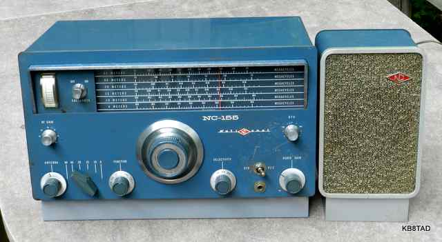
The NC-155 was introduced in 1961 at a price of $199.95. It was reviewed in QST magazine in July 1962. The matching NTS-3 speaker was an optional accessory. The NC-155 and its speaker both have the "flip-foot", a flip out stand for the front of the set to angle the desk-mounted receiver and speaker up toward the operator.
Condition
The overall cosmetic condition of this set was fair but the set was totally inoperative. However, the hamfest price was in accordance with the condition.
Repairs
The set was dead due to an open power switch. That is a fairly common problem in a long-dormant set. An application of deoxit solved that problem. Although the set could now power-up with the tubes lighted, it was still inoperative. I traced the B+ line to what I assumed was an open Standby-Receive switch. However, the Standby-Receive switch turned out to be a DPST replacement that was mis-wired. The B+ feed was incorrectly swapped to a terminal strip on the rear of the chassis that was meant to control an external relay when switched to the standby position. I temporarily rewired the DPST switch to properly control B+ but later replaced the switch with a DPDT version so that external control of a relay when in Standby was possible again. There are a couple of scratches in the front panel near the Standby-Receive switch so I suspect the former repairman may have used the wrong tool to remove the original switch.
The capacitors in this set are mostly ceramic so only a few needed replacement.
Alignment
After repairs to the Standby-Receive switch, the set was operational primarily on AM. The biggest problem was the BFO which was very far off. The first clue; the BFO had to be maxed at the upper sideband position in order to barely function on lower sideband. The fix was relatively easy, simply re-aligning the BFO. The rest of the set was out of alignment as well. The 230 KHz second IF was surprisingly accurate. I had read of others who had problems getting the ferrite filter to align at 230 KHz, but that was not a problem in this set. However, the 2215 KHz first IF was off by over 40 KHz. I re-aligned it and then proceeded to align the various ham bands. Note that the manual has a serious typo in the alignment instructions. Step 6 lists the mixer slug for 21 Mc. as T-1. It is actually T-7. You can verify by comparing the alignment instructions for the NC-270. T-1 is adjusted in Step 4, the antenna slug for 28 Mc. The schematic also has an error, mis-identifying the tube numbers in the filament circuit. Not a serious error but confusing.
Because of the sets poor IF alignment, a prior owner had tightened the little mixer trimmer caps to the max. I had to use a screwdriver to loosen the trimmers. With the proper IF alignment, the peak for each trimmer was about a quarter to a half turn less than maximum tightness.
After alignment, the set was a joy to tune for SSB conversations. I listened to a number of SSB conversations on the 20, 40 and 80 meter bands. However, I noticed that the power transformer was getting uncomfortably hot after about an hour or so.
A hot transformer
While the manual specifies a voltage rating of 105 to 125 volts, it also specifies a power draw of 75 watts. The actual power draw at 120 volts was 90 watts. The B+ voltage line is specified at 160 volts on the schematic. Even with my variac at 115 volts input, the B+ was actually about 10% high.
I decided on a circuit modification, something I rarely do. I added a 150 ohm resistor between the 5Y3 rectifier and the first electrolytic. That reduced the B+ to the specified 160 volts with 115 volts AC input. As expected, it also reduced the power draw by a couple of watts. The transformer still gets hot but a bit less so. I recommend using a bucking transformer or variac to reduce the AC input for all boatanchor radios but especially so for this one. I would not operate it for any length of time at a voltage higher than 115 and preferably somewhat less. Since its voltage rating notes 105 volts as the lower end, running it at that level will not affect performance. For more information on the transformer problem, see the notes under the NC-270.
What are those other resistors doing?
The NC-155 circuit has a 470K ohm resistor and a capacitor wired between the unswitched side of the power line and the chassis. I assume the purpose is to protect the power transformer in case of static discharge from an antenna but you can feel the effect when touching the chassis. I decided to polarize the power cord so that the unswitched side, and that resistor-cap combination, would only see the neutral side of the power line, eliminating the problem.
The speaker line has a permanent 33 ohm resistor across the secondary. I have always thought that such a resistor should have been standard equipment on any vacuum tube radio (or audio amplifier) with a separate speaker or headphone jack since it would provide a small constant load protecting the output transformer and tube from high voltage transients in the event of a missing speaker load.
Performance
After repairs, alignment, and the slight modifications, the NC-155 proved to be a very good receiver for SSB on 20 to 80 meters. The set was quite stable with minimal drift after a relatively short warm-up time. The big fly-wheel dial was smooth in tuning and a pleasure to operate. The 20 meter sensitivity was especially good as I was able to hear SSB conversations with just a foot or so of wire on the antenna in between the steps called for in the alignment instructions. That was of course in daytime hours, prime time for 20 meters.
The 6 meter AM performance was marginal with poor sensitivity. Perhaps I have been spoiled by the likes of very good vintage 6-meter-only AM tube transceivers such as the Gonset Commmunicators, the Polytronics Poly-Comm 6 or even a Heathkit Sixer. The NC-155's 6-meter performance is simply not in the same league as those sets. Of course, those AM transceivers cannot do SSB.
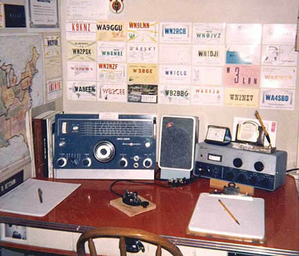
NC-155 in a vintage hamshack
Here is a picture of the NC-155 in the 1965 Novice shack of WB2RCB along with his Knightkit T-60 transmitter .
Manual source
A manual and schematic for the NC-155 can be found on BAMA. See the homepage for a link.
Date 6-1-12
A Knight Ocean Hopper regenerative receiver was the previous item on the bench.