A variable high-voltage regulated power supply is always useful for testing and repairing boatanchors and especially useful if it has both regulated and unregulated filtered power for devices such as homebrew transmitters.
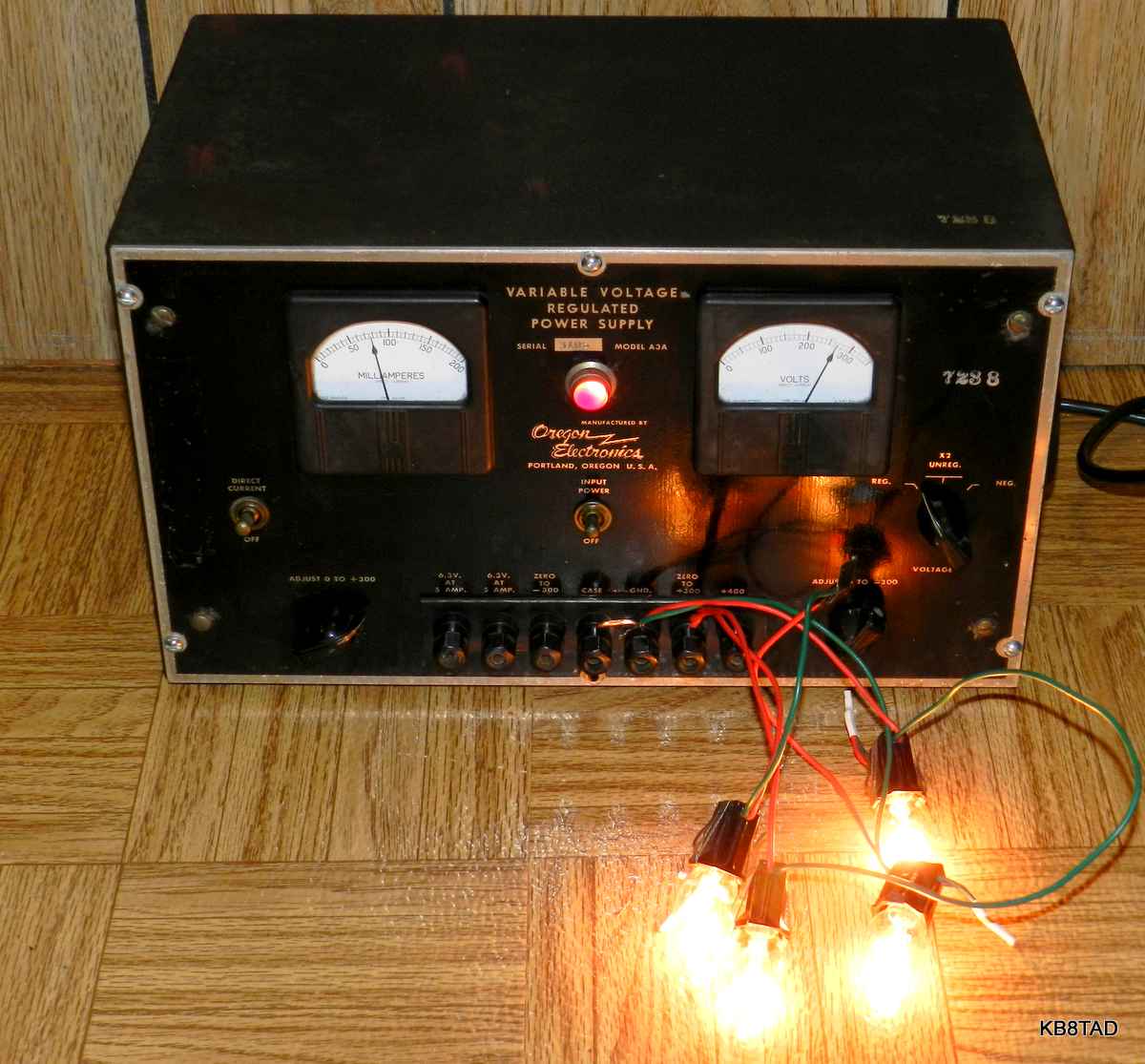
This Oregon Electronics A3A is a lot of power supply in a small package, measuring only 14 inches wide. It is rated for 200 mA at 400 volts unregulated and zero to +300 regulated. It also has a low-current 0 to -300 variable bias source. It was purchased at a very reasonable price at a hamfest (ham radio swap meet). Both current and voltage are metered. A switch selects among the three sources for voltage metering.
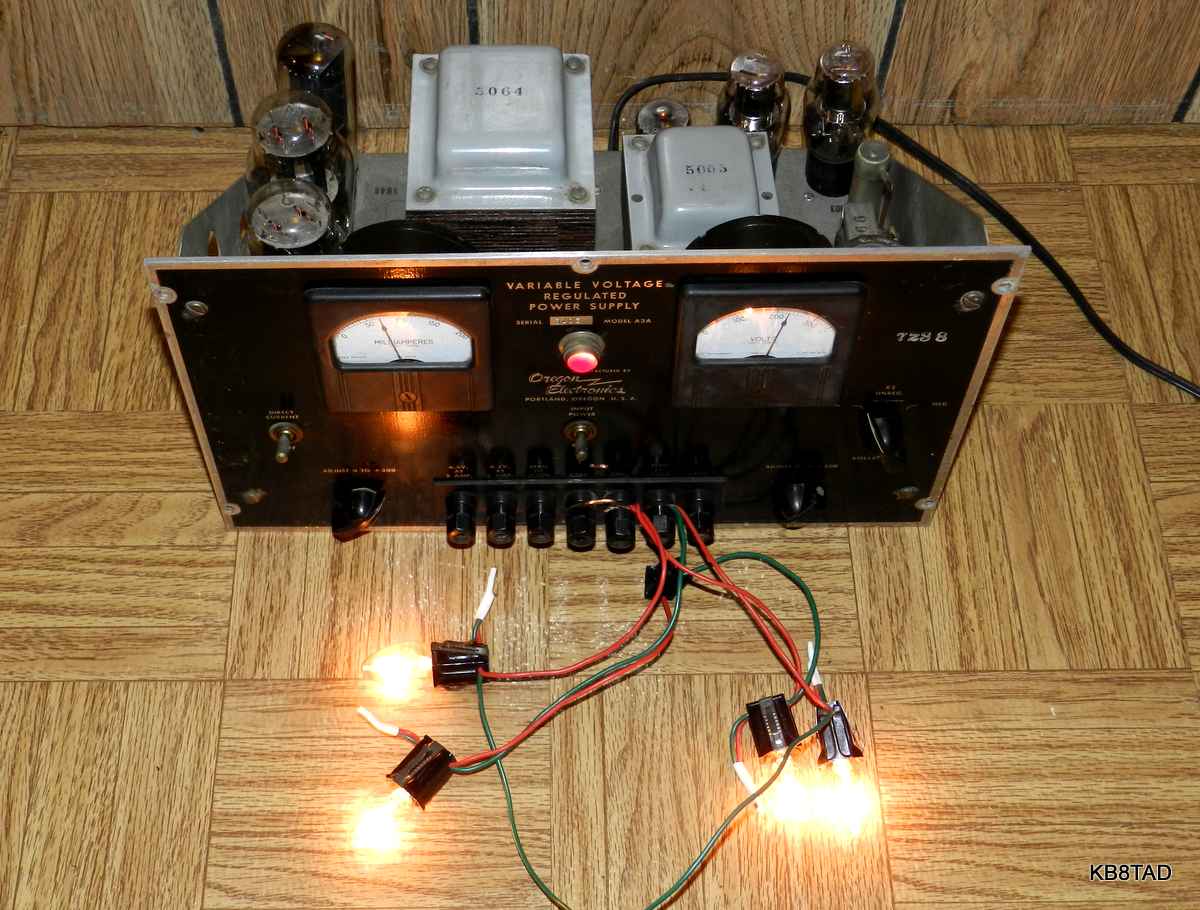
Although this power supply is relatively small, the transformer and choke are beefy as might be expected with 200 mA continuous current handling capability. A 5U4GB is the main B+ rectifier and a 6X5 supplies the separate negative voltage source needed in order for a regulated supply to regulate down to zero volts. Two 0D3 gas regulator tubes in series supply regulation at -300. That negative voltage is used both as a reference and as the source for the variable C- bias supply with a 70K ohm potentiometer to vary the output from zero to -300 volts. The control tube is a 6SH7 pentode metal octal and the pass tubes are a pair of 6B4 power triodes.
Caution- High Voltage
Regulated power supplies use lethal voltages, in this case from -300 to +440. That adds to 740 volts between certain points in the circuit. A healthy respect for high voltage is a necessary attitude for any vacuum tube boatanchor device but especially for regulated power supplies.
Repairs
Thanks to Scott T. for the schematic and the instructions for this piece. If you have one of these power supplies and need that information, send an e-mail to the address on the homepage.
Preliminary checks showed no continuity between the prongs of the power plug when the device was switched to "On". That is increasingly common and is probably why it was sold at a reasonable price at the hamfest. As I expected, the power switch problem was easy to cure with the device on its back and some DeOxit in the switches via the bat handle openings. I also opened and cleaned the erratic negative bias pot.
After safety checks, I powered it up slowly. It was working but the regulated variable side would not go to zero. Its minimum was about 80 volts. I replaced the 0.1 uFD 1000 volt anti-hunt cap at the regulated voltage control thinking a bit of leakage would throw the high impedance control circuit off somewhat. That did not solve the problem. I have experienced similar control circuits in the Heathkit PS-4 and IP-32 regulated supplies. Heath includes two onboard controls for setting the zero and the highest voltage points. The on-board pots are part of a series resistor string between the high positive and high negative sources with the voltage control pot at the center. The Oregon circuit does not have on-board adjustment pots. I temporarily bridged the 220K resistor that is in series with the voltage control with another resistor starting with 470K ohm and working down to another 220K at that control which tamed the problem for the most part, but the voltage would still not go down to zero, hovering at about 18 volts or so instead of zero. I swapped the 6SH7 with a NOS version and tried swapping in a known good 6B4. I also tried bridging the other resistors to slightly alter the parameters but no changes. I had read on the net of someone else's similar results, not being able the get the regulated voltage control below 20 volts. Was my result the norm for this piece? I doubted that. It had apparently worked fine at some point in time with the existing resistors, none of which had drifted significantly.
The Eureka moment
I then replaced the 40 uFD dual section electrolytic. To my surprise, that solved the problem. It now zeroed fine. I then removed the added resistor and the circuit continued to work as designed. The difference? I concluded that apparently the regulated voltage circuit is VERY sensitive to ripple voltage and that was likely the cause of the problem.
I replaced the power cord with a new three-wire version, rewiring the set for modern standards (line goes first to fuse, then to power switch, the neutral goes directly to transformer and the green safety ground to chassis)
Cosmetically the classic face of the supply had several remnants of stuck-on paper labels. All the paper labels and the dried glue came off with Goo-gone and some careful scraping with a non-marring wooden stick.
Alternate pass tubes
While the schematics for both the Oregon A3A and the earlier A3 model show the 6B4 triode pair used as the pass tubes, each schematic and the chassis itself also show tube terminal connections for a substitute tube pair with wires going to what would have been an indirectly-heated cathode at pin 8 and a screen grid connection at pin 4. The 6B4 has no connections at those pins. Model A3 as shown by the RadioMuseum.org site has a pair of 6L6 tubes. Oregon lists the 6B4 is an alternate in that earlier model. The 6L6 can be used in model A3A as well. Given the current prices for both the 6L6 and the 6B4, I may try a pair of less-expensive plug-compatible 6Y6 favored by other manufacturers such as Lambda.
The 6Y6 was also used in the Neustadt voltage regulated power supply patent.
The same socket connections would also work for a pair of 6DQ6, another less expensive and relatively easy substitute which some owners have already installed with a modification of feeding plate terminal at pin 3 to the top cap.
Testing the supply
Like previous power supply tests, I used a light-bulb load, in this case two series pairs of C-7 Christmas lights cut from a Christmas light string. C-7 bulbs are also sold as night lights. Each series pair of C-7s can readily handle up to 300 volts at about 50mA without undue stress. The Oregon supply easily handled the load.
Specifications for the supply
The filament source of 6.3 VAC has a front-panel current specification of 5 amperes. For high voltage, the supply is rated at 200 mA. That is the total for both the unregulated and regulated output. Although the unregulated side, which measured at about 440 volts at no load with my line voltage, can easily handle 200 mA at 400 volts, the pass tubes are the limiting factor on the regulated side. The two 6B4 can together handle a total of 30 watts dissipation. The Oregon manual information shows that the variable side can indeed be loaded to 200 mA as long as the output voltage is at least 250 volts or more. At that load and voltage, the pass tubes drop a total of 150 volts, down from 400 to 250 volts, at 200 mA which is 30 watts. At lesser voltages, the maximum milliampere specification is based on that same 30 watts maximum so at 100 volts, the pass tubes are dropping 300 volts, therefore the maximum load is limited to 100 mA.
The Heathkit PS-4, IP-32, and IP-17 each use a pair of 6L6 pass tubes and are rated at 100 mA with an upper voltage maximum of 400. They are similarly limited at low voltages.
Operating the supply
For an all-around bench supply, the Oregon will see a great deal of use. Its 7 pin rear-panel jack makes for an easy semi-permanent connection to a home-brew transmitter or amplifier. It has no built-in time delay. Main power is switched on first and then after tubes are warmed, the DC switched is turned on. Leaving the DC switch on during main power-up allows the regulated side to go high for a couple of seconds before the regulation circuitry kicks in. I suppose that is caused by the directly heated 5U4 and the 6B4 pair coming up to power more quickly than the heated cathode tubes (6X5 and 6SH7). Perhaps substituting the pass tubes with indirectly heated cathode tubes might lessen that slight time-delay difference. In the meantime, the handy DC switch quickly cuts off high voltage, partly due to the large 20K ohm bleeder.
Other regulated power supplies
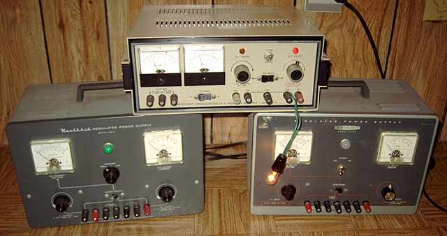
Click here for information on a very heavy duty regulated high voltage supply by Kepco.
Here are several Heathkit high-voltage regulated power supplies with similar circuitry to the Oregon A3A.
date: 8-5-15, update 8-9-15, 10-1-15
The Astron VS-35M low-voltage high-current variable DC power supply was the previous item on the bench.