
Its first job was at NASA.
An RF spectrum display (for rocket scientists)
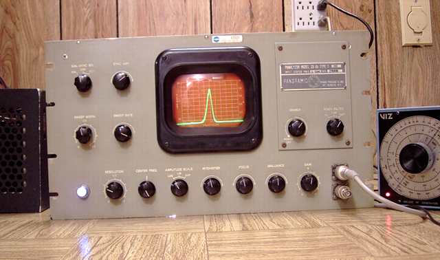
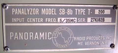
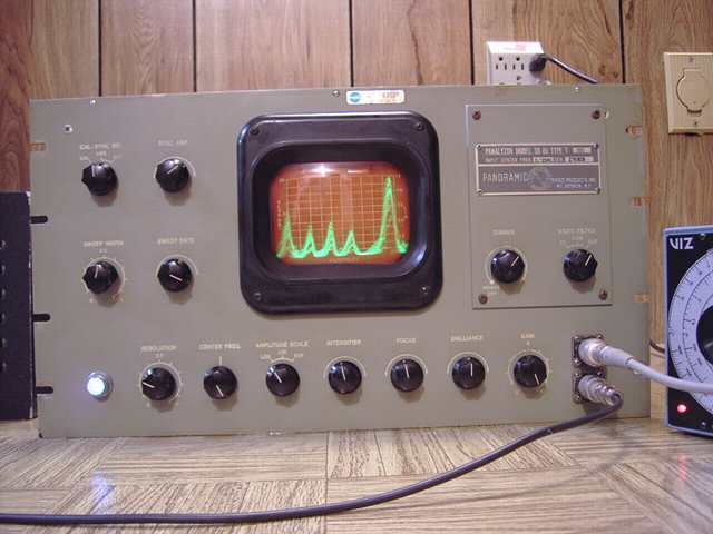
The Panoramic Radio SB-8b Panalyzor type T-200 is an early spectrum analyzer. This particular piece was used by NASA's Goddard Space Flight Center at one time according to the property tag on the piece. These were used for monitoring telemetry signals from orbiting space capsules (details below).
The SB-8b has 16 vacuum tubes plus its CRT (cathode ray tube). It is an improved late 1950's variation on a Panadaptor, a device first used during World War II for viewing a selected segment of radio frequency spectrum for various signals. All panadaptors were designed by and based on patents held by Panoramic Radio Corporation.For a WW II version, see the Signal Corps BC-1031C repaired earlier.
I have also repaired a smaller postwar commercial version, the Panadaptor model PCA-2 T-200 .
All of the panadaptors required a companion radio receiver and were limited to a specified IF frequency such as 455 KHz. However, the Panalyzor goes one step further.
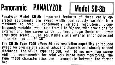
"Panalyzor + External Signal Generator = Low-cost RF spectrum analyzer"
So reads the ad for the SB-8b. The Panalyzor adds a 6BE6 converter circuit and a broadband RF amp which allows for viewing any 200 KHz segment by using an external RF signal generator to set the frequency of choice. According to the manual, the device is usable in such a manner "up to 1000 Mcs" (1 gigahertz).This SB-8b has a base input frequency of 500 KHz and is set to display signals in a spectrum of + to - 100 KHz from the base 500.
Connection to RF test and signal generator
The SB-8b connects to a device under test and the companion signal generator by coax and a pair of "N" input connectors. Those inputs are terminated by 51 ohm resistors and feed two of the 6BE6 grids.
The signal generator and the Panalyzor are adjusted so that the signal of interest is at the center of the display. Signals in the range of the signal generator frequency plus (or minus) 500KHz show up as pips of varying shape to the left and right of center. Pip shapes vary with the type of transmission. The height of each pip varies with signal strength. An AM signal shows up as a pip that has variations in height and visible sidebands in step with the modulation. As the signal generator is varied, the pips move to the left or right depending upon whether the signal generator is lower or higher than the frequency of interest.
Building a power supply from junk-box parts
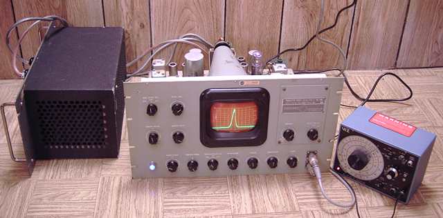
This unit came without its power supply. I could not test it without proper power so the first task was to build a power supply with three separate 6 VAC supplies for the filaments, 260 volts at approximately 125 mA for B+ and the very important -1800 volts for the CRT. (Homebrew power supply is the black box on the left in the picture.) The "boxe de junque" yielded a good-sized power transformer from an old Dumont oscilloscope and a recycled rack mount chassis. The transformer had the very high voltage winding and the separate 6 volts at 0.6 amp CRT filament winding that carries the negative high voltage bias. It only had one other 6.3 VAC winding for tube filaments. However, it had two separate 5 volt windings each capable of 2 amps. I paralleled those windings. At no load, the voltage was about 5.8. I decided to use that for the third 6 VAC filament source.
Repairs
Before connecting power, I had already cleaned the Panalyzor, all of the tube pins, sockets, and controls and had tested for low resistance in the B+ and high B-- circuits.After the power supply was built and tested, I connected the Panalyzor.
While the glow of the filament in the CRT was visible, there was no display on the screen. After a couple of minutes the current draw on the B+ rose rapidly. I shut the unit down. The culprit turned out to be a leaky three-section 0.1 MFD capacitor. I replaced it with three separate 0.1 caps, leaving the three section chassis-mount cap in place for cosmetics.
Replacing the caps stabilized the B+ but still no screen display. In trouble-shooting the CRT controls, I found a focus control that was apparently shorted, reading about 10 ohms instead of 500,000. I removed the control, opened it and cleared out the conductive dust or dirt. That solved the focus control problem. Still no indications on screen. I finally pulled the horizontal and vertical amplifier tubes and checked to make sure that the voltages on the horizontal and vertical deflection plates were identical. This was to see if a single spot could be produced on screen. Still no display. Conclusion, bad CRT.
Replacing the CRT
I did not have a 5UP7. However, I did have a spare 5DEP1 that was identical in size from a defunct scope. It was also plug-compatible with the same socket pinouts. The main difference was that it had P1 phosphor (green) instead of P7 phosphor (white). That CRT substitute finally showed a spot that could be focused and moved by the deflection circuits.
Horizontal deflection
Both the horizontal and vertical adjustments were off. The vertical adjustment was simple but the chassis-mounted horizontal control was at the extreme setting and still would not show more than a small amount of a trace. Changing resistors and adding a bit of resistance in one case solved that problem. After a few adjustments, I was delighted to see a horizontal line with a bit of "grass" (random noise) when the gain control was turned up fully. To my surprise, no other repairs were needed. The instrument was working as expected.
"Playing" with it
After repairs I found the Panalyzor fun to experiment with. The SB-8b has a full screen sensitivity of just 200 microvolts. A quarter inch display needs only 20 microvolts. I connected just an antenna to the coax connector and was able to see signals in the form of pips on the display. I next connected a signal generator and tuned in local AM radio stations, watching the action of the modulation on the pip height and the visible sidebands.
I found that I could indeed view just about about any spectrum segment within the range of my signal generator.
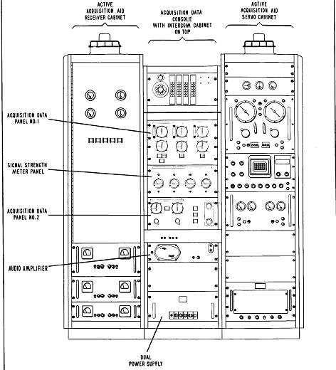
As Used by NASA in Project Mercury
NASA used the generic term "panalyzer" in place of panalyzor. Panalyzor (spelled with the "o") may have been a trade name. The 7 astronauts known as the "Mercury Seven" included John Glenn, the first American to orbit the earth, circling the globe three times aboard Friendship 7 in February 1962.
Quoting NASA archives,
Here is a diagram from NASA archives showing the SB-8b in the telemetry console.
Quoting NASA Archives again, here are the instructions and procedure for receiving:
I don't know whether this particular SB-8b was used at one of the Mercury sites. However, it could have been given its 35 MHz input capability.
More info on Panadaptors
For lots more info on Panadaptors and the Panoramic Radio Corporation, see the excellent writeup by Chuck McGregor N7RHU Chuck alerted me to the existence of the schematic for the SB-8a which was close enough for use. That manual is on BAMA under Panoramic but is labeled IP259 which is the Signal Corps designation for the SB-8a. He also sent a copy of an ad containing specifications for the Panalyzor. Thanks Chuck.
BAMA has the manual in PDF form.
A Stromberg-Carlson SP-965-C "Integrity Series" console made with discrete audio components was the previous project on the bench.