Fun With Signal Generators
The following article was first published in the September 2013 issue of Monitoring Times of Brasstown, North Carolina.
I have added some additional images on this webpage that could not be included in the article due to space limitations. The article is copyrighted and may not be reproduced without permission of Monitoring Times or the author.
Fun With Signal Generators
by Rich Post KB8TAD
I recently acquired another service-grade signal generator from the vacuum tube era, a Simpson 415A to go with my Simpson 315. I now have more than a dozen different types including a Heathkit SG-8 and IG-42, an Eico 315 and 324, a couple of Precision E-200-C, several from RCA including one from their home study electronics course, and even a military URM-25D. With the exception of the URM-25D, the price was right, usually less than ten dollars for one in "as-is" condition. Besides the low cost, what is it about a signal generator that has so much appeal to me as well as to other radio experimenters and antique radio enthusiasts?
A gathering of signal generators.
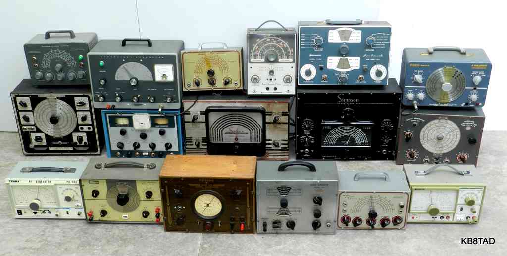
- - Top left to right; Heathkit SG-8, Heathkit IG-42, Heathkit G-1, Lafayette KT-208, Superior TV-50A, Paco G-30 - -
- - Middle; Precision E-200C, Realistic TK-100, Simpson 315, Simpson 415A, Superior 660 - -
- - Front; Tenma 72-585, Olson TE-188, Supreme 570, Eico 324, Heathkit SG-6, Leader LSG-17 - -
My first signal generator
As a kid, I was fascinated by radio. In eighth grade, I had built my first Heathkit, a four band
AR-3 radio receiver. It was a superheterodyne that needed alignment. A ham radio operator aligned it for me, but I wanted to learn how to do that myself. Seeing an
SG-8
in the Heathkit catalog for about $20, I knew I wanted to build that next. After completion, the kit worked right from the start. I read and re-read the manual section on the circuit and how it worked. I learned that it was a little tunable transmitter. While it was normally connected by clip leads to radio antenna terminals with a small capacitor, it could send a signal to a radio even without a direct connection. I could switch on the internal modulation and connect a telegraph key between the output clip lead and a piece of wire as antenna and practice sending code to a radio.
The manual also showed how to inject a signal to check each radio stage. I made sure I had a capacitor at the very tip of the output lead to block any B+ from the radio under test.
Calibration accuracy for alignment
The calibration of the SG-8, like most service-grade signal generators, was less than accurate, but I learned how I could tune the generator to zero beat its signal on top of a radio station, typically a weak signal station whose frequency was known. The signal generator was then accurately tuned to the same frequency as that station and I could make a note of the off-set as compared to the dial indication.
I also learned about harmonics. I had an older Silvertone radio that used an intermediate frequency of 465 KHz. I wanted to make sure the generator was putting out an accurate 465 KHz signal for aligning the IFs. I found a station at 930 KHz which is double that 465 KHz frequency. Tuning the generator to about 465, I used that second harmonic which was exactly twice 465 to zero-beat on top of that 930 KHz signal.
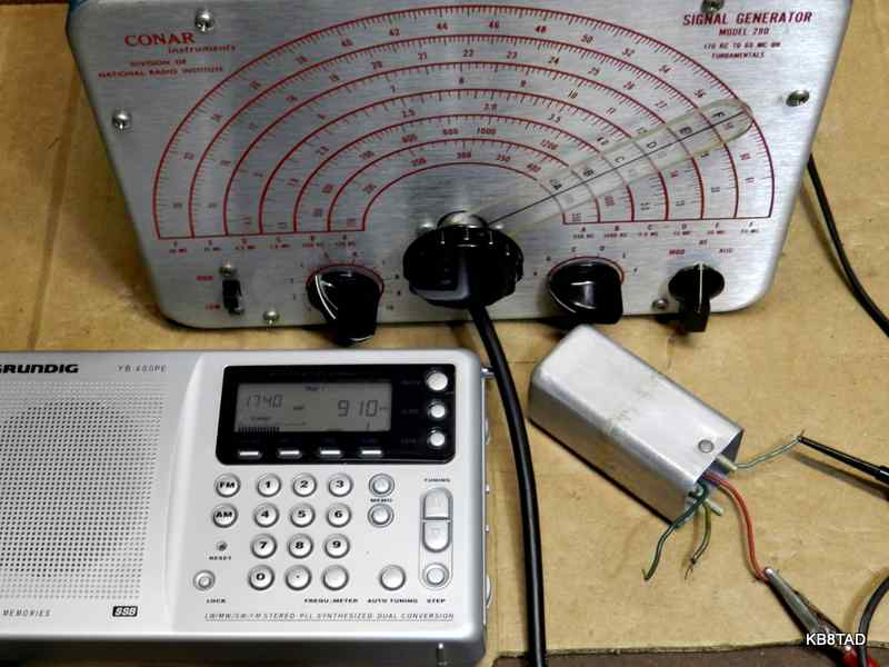
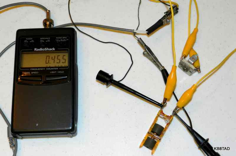
These days, with accurate digitally-tuned radios such as my little Grundig YB-400PE, calibration accuracy is even simpler. I just set the Grundig to the desired frequency and tune the generator to zero-beat with a broadcast station at the Grundig's frequency or to maximize the radio's signal strength indicator.(Fig 1) Of course, for those who have a frequency counter the question of calibration accuracy is even simpler.
Fig 1 - A Conar 280 signal generator is tuned to exactly 455 KHz as indicated by zero beating
its second harmonic at 910 KHz on a Grundig YB-400PE digitally-tuned radio
But what else can be done with a simple signal generator?
The Heathkit SG-8 had an input for external modulation. I learned that I could feed music from my hi-fi amp speaker output to that external modulation input using a little matching transformer. The signal generator would then broadcast that low-level signal to a nearby radio as a mini broadcasting station. I clipped an unshielded wire onto the RF output for an antenna and draped that behind the radios I wanted to receive the signal. Fun stuff for a teenager!
Shortwave receiver with no BFO
I also used the signal generator as a substitute BFO for a short wave radio without one. Tuning the signal generator either to the IF frequency of the radio or very close to the actual receive frequency would allow me to make SSB signals intelligible. Just draping the output lead near the shortwave antenna wires was usually enough injection, but I could also feed the output to an insulated wire wrapped around the mixer tube.
As an adult, I learned a few more tricks with the signal generator. I had some quartz crystals for specific frequencies but did not know if they were active or not. By now, I had acquired a frequency counter and an oscilloscope. I connected the outer coax shield wires of the scope and the generator together and clipped the crystal between the RF output of the generator and the scope input lead. A direct scope probe is fine.
Fig 2 - Testing 1843 KHz crystal using a Paco G-30 signal generator and a Heathkit SM-2420 Counter.
The scope is a Tektronix 2445 but low-end scopes will work as well.
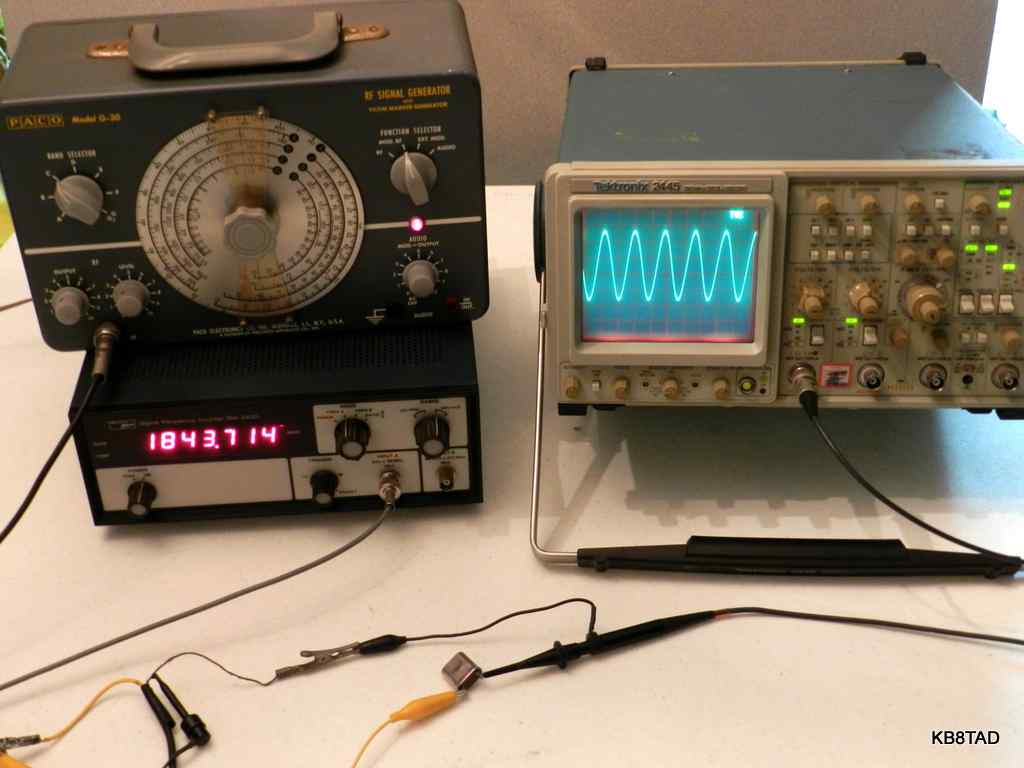
Tuning the generator frequency very slowly near the crystal frequency caused a very sharp sudden increase in signal level as viewed on the scope as I crossed the resonant point of the crystal. The simple connections made it easy to test a number of crystals.
A friend told me of a time when he needed to trace some intercom wires in the walls of his house to find a break in the wire. He connected his signal generator to the one end of the intercom wires and used a pocket transistor radio to trace the wires to the point of the break. I considered that a slick use of a signal generator. If you try this, make sure there is no power on the wires being traced before clipping a signal generator on one end of the wires.
In the June 1954 CQ magazine, Howard Burgess W5WGF wrote an article on various uses of the signal tracer. One of his tips was using a tracer with a signal generator to determine band pass frequency characteristics of an IF transformer or resonant circuit. For a better result, I prefer to use a signal generator and scope with a low-capacitance probe for this purpose. Excellent scopes are considerably cheaper and more capable than when Burgess wrote that article. Using the generator and scope to observe the resonance characteristics of the typical tube-radio IF transformer is similar to testing crystals. The primary connections of the IF transformer are connected to the signal generator and the secondary side to the scope. Tuning the generator across the IF transformer's resonant frequency causes an obvious increase in signal level as seen on the scope. The exact resonant frequency for an IF transformer may not be accurate because even the low-capacitance 10X scope probe will affect the actual resonant frequency. The probe causes the typical 455 KHz IF transformer to drop its resonant frequency somewhat, typically about 5 to 10 KHz or more.
I had some loose IF transformers in the junk box. I could determine proper phase relationship between primary and secondary. Proper phasing showed the highest voltage gain at resonance. I could also estimate the approximate band pass. However, I could not determine which terminal side was the primary and which the secondary so I had to rely on wire color codes or the green paint mark on the IFs for that information. In a mixed set of If transformers as removed from circuits, I could easily distinguish those in the 400-500 KHz ballpark versus those that were significantly higher, a handy way to check a batch of mixed IFs from the junk box. If you don't have a low-capacitance probe, try a 10,000 ohm resistor at the scope probe tip to limit loading.
Checking resonance
The resonant point of just the IF transformer primary or secondary can be also be checked individually. Just connect the coax shields of the generator and the scope together and clip the scope low-capacity probe and generator output leads across either the primary or the secondary winding. Using that connection, I was able to determine that one side of a particular IF in the junk box would not peak at the proper frequency. I recall purchasing an auction box lot with some used IF transformers. In hindsight, that IF was probably removed from a radio because it would not peak when aligned, most likely due to silver migration disease.
Checking for silver-migration disease in IF transformers
A silver migration problem occurs in smaller IF transformers in vacuum-tube circuits, typically those about 3/4 inch wide using adjustable cores and fixed mica capacitors. Those capacitors have a silver coating on mica sheets but, unlike the typical mica capacitor which is encased and sealed in an insulating material, the capacitors inside the IF are exposed. Silver migration is hastened by humidity in the presence of an electrical field. A radio with the IF silver migration problem usually exhibits a continuous loud static or crashing noise that is not reduced when the antenna is disconnected or shorted. However, the noise can be reduced by the volume control. Weaker stations are often totally masked by the noise. I have also seen cases where migration so deteriorates the IF transformer that even without the static, the sensitivity of the radio is extremely reduced and the IFs can no longer be aligned to proper resonance.
Since the simple scope and signal generator hookup to test an IF transformer primary or secondary can also be used on an IF transformer still in the circuit of an unpowered radio, I found that to be a valuable quick check. I had a Hallicrafters 5R34A �Continental� bakelite radio circa 1951 on the bench and had suspected an advanced case of silver migration. (Fig 3)
Fig 3 - Testing the first IF primary winding of a Hallicrafters 5R34A "Continental".
A quick check of both IF transformers in the unpowered set showed both sides of the second IF to be in good order, but the primary of the first IF would not show resonance until the signal generator was at nearly 800 KHz, confirming my diagnosis of a seriously deteriorated silver mica. It took just a few seconds to test each winding. The surprise was that only the primary of one IF was affected. I had expected a problem in both IF transformers.
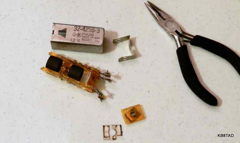
Years ago, a radio repairman would just replace bad IF transformers. New replacements are now scarce. It is not that difficult to open the bad IFs, remove the offending silver mica capacitors, and rebuild the IF transformer with a new capacitor either inside the shield or, my own preference, under the chassis. (Fig 4)
Fig 4 - IF transformer opened to remove exposed silver mica capacitors.
The same signal generator and scope check can be used to verify that the repaired IF transformer primary or secondary will resonate properly with a temporary capacitor clipped into place before reinstalling the transformer. That temporary capacitor can be a variable compression trimmer whose value in picofarads can then be read for a permanent fix. (Fig 5)
Fig 5 - Testing an IF transformer winding to determine capacitance needed at 455 KHz resonance by adjusting a trimmer capacitor on clipleads. With the ferrite slug at its center, the needed cap measured 180 pF. With the slug at its extremes, the needed cap ranged between 160 and 202 pF.
In the same manner as testing the primary or secondary of an IF, other resonant circuits can also be checked. The resonance of the antenna section of the typical tuning capacitor can be readily checked in an unpowered radio. With the coax shields of the signal generator and the scope connected together, the generator output lead is connected to the variable cap stator and the scope input is connected to the rotor, typically the radio chassis. Moving the capacitor with the tuning knob will vary the resonant point as observed on the scope. Shorts or poor and intermittent rotor contacts can be easily found.
Fixing up nice old service-grade signal generators
Most of the signal generators I have repaired have problems similar to typical radios of the tube era; dirty connections and controls, bad capacitors, and an occasional drifty resistor. Bad tubes and power supply problems other than electrolytic capacitors are rare because signal generators typically have seen much less use than a radio of the same age. Applying contact cleaner such as a bit of Deoxit to the bandswitch contacts, the potentiometers and tube pins and their sockets solves many problems. Wax and other leaky tubular capacitors should be replaced and possibly the electrolytic. The test leads should be checked for proper connections. I suggest replacing the power cord with a 3 wire version with safety ground.
I once deliberately purchased a cheap Eico 324 in awful cosmetic condition. It had a large Hallicrafters knob on it that was worth the two dollars I paid for the piece. After swapping knobs, I wanted to see what it would take to make the Eico perform. After cleaning all contacts and carefully powering it up, I found that the audio modulation did not work. Replacing the two capacitors connected to the audio inductor repaired the piece. I replaced the other wax caps as well. A thorough scrubbing of the front panel and spray-painting the cabinet made it look decent again. I still use it.
Experiments as AM broadcasters
The Simpson 315 is unusual since it is has a separate 6C5 oscillator tube and a 6K6 as buffer/ power amp. It used a separate transformer for screen modulation of that 6K6. That transformer had three windings one of which was open. I doubted that I could find a replacement so I decided to have some fun with the piece. I replaced the open transformer with a reversed audio output transformer and fed it with audio from an amplifier. I also bypassed the attenuator and directly fed a home-brew loading coil and 10 foot piece of wire from the 6K6 plate capacitor as a simple broadcaster. Going outside with a portable radio, I found I could still hear the signal at over 250 feet from the house. I estimated the power input to be several times what was allowed for a part 15 broadcaster. I was surprised at the result but, not wanting to break the rules for part 15, I quickly shut the Simpson down! I have since located a proper substitute for that transformer.
After learning of my experiments with signal generators as broadcasters, I received the following e-mail from Tom WA0EAJ. I had a good laugh reading his story.
"While going to Radioman "A" school, at the US Naval Training Center, in San Diego back in 1962-63, we had an old Chief who simply LOVED that whiney, nasal, my-sweetheart-ran-off-with-my truck-driving-best-friend-in-his-Peterbilt kind of country music. The station he listened to repeated the same stuff OVER-AND-OVER....EVERY DAY. One day, we got hold of an AN/URM-25 signal generator, and poked classical music into the "external mod" connections, and zeroed it on his AM station. He came back into the room, and there were the sterling sounds of a mezzo-soprano GRAND OPERA singer, doing Wagner, no less. He almost had a seizure right there... of course, he moved the tuning to another C&W station, and shortly thereafter, we zeroed in on that one too. This went on for about an hour, until we heard a crash... looking out of the window of the code-transmission room, we saw the remains of his old radio - scattered on the pavement. The URM-25's I see at hamfests always make me chuckle, now."
After laughing at Tom's story, I checked my own URM-25D to test its capability as broadcaster. I found it works extremely well with no conversion needed. It has both a high level output and a standard low-level output of 0.1 volt at 50 ohms. The high level jack provides 2 volts of signal at 500 ohms impedance. That's about 8 milliwatts of RF out, about 40 times the power at the standard output. The high level output is still within part 15 rules. Keeping the modulation level to a maximum of 50% on peaks makes for a nice-sounding signal.
Nearly any signal generator with an external modulation input can be used for a simple broadcaster. To maximize the signal strength for this purpose, I feed the normal low impedance RF output into a simple loading coil and then connect 10 feet of wire for an antenna. (Fig 6) A simple capacitor compression trimmer can be added in series between the coil and the antenna wire to increase the self-resonant frequency or in parallel between that antenna side of the coil connection and signal generator ground to decrease the resonant frequency. The resonant point can easily be seen as a voltage gain using a low-capacitance probe at the antenna and coil connection point. The scope pattern at resonance will be a relatively clean sine wave as compared to the normal harmonic rich output of the signal generator which seldom looks like a sine wave. Harmonics will be reduced to minimum at the resonant point. Feeding the signal generator with an external audio input results in a useful low-powered experimental broadcaster.
Fig 6 - Natural resonance of 244 microhenry loading coil (a broadcast oscillator coil) and 10 feet wire (left clip lead) is 1320 KHz. The scope dual trace shows Eico 324 signal generator output (lower trace) and loading coil sine wave output (upper trace)
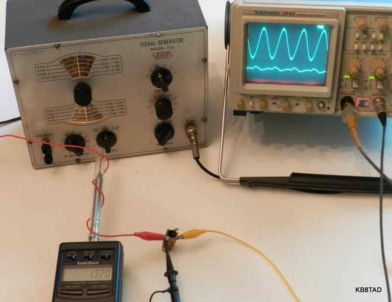
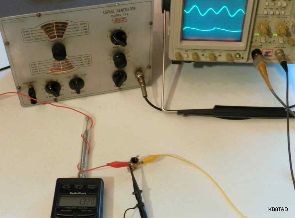
Using an Eico 324 signal generator and an oscillator coil of 244 microhenries from a parts radio, I found that the natural resonant frequency was 1320 KHz. I noticed that if I fed the resonant coil and antenna at exactly half that frequency, my frequency counter would still show the same resonant frequency. (Fig 7) That makes for a simple demonstration of a resonant circuit's ability to double as is often done in transmitter finals. The scope patterns can be shown to new hams learning the basics to teach about resonant circuits and frequency doubling or tripling stages.
Fig 7 - Frequency doubling. The Eico 324 is feeding 660KHz but the loading coil shows resonance at 1320 KHz. The scope signal generator output (lower trace) and loading coil output (upper trace) shows one signal generator pulse for every two sine waves.
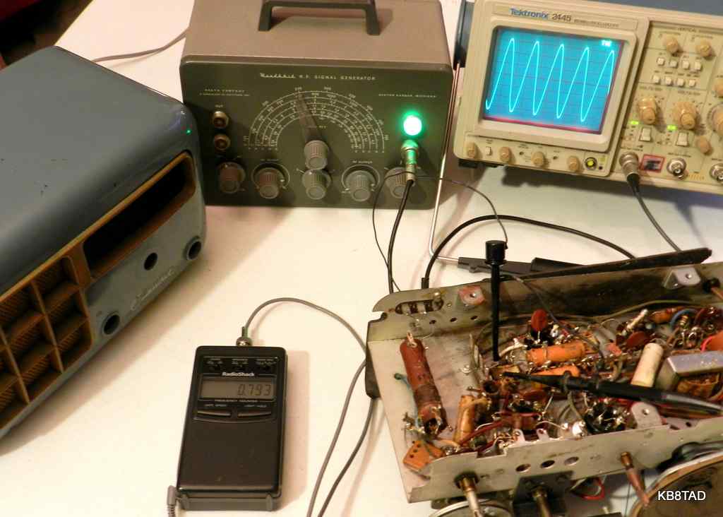
My personal favorite signal generator for conversion to broadcaster is a Superior Instruments Genometer TV-50. The TV-50 was heavily advertised on the back pages of Popular Electronics during the mid 1950s. The circuit used what were surplus computer tubes at the time. That was a lucky choice. The TV-50 uses a 6B1000, a dual control tube perfected by IBM and its vacuum tube suppliers for computer use. Dual control tubes make about the best tube-based Part 15 AM broadcasters as determined by a number of experimenters on the Antique Radio Forum. The dual control tube is capable of 100% modulation with minimal distortion. I substituted another dual control tube, a directly plug-compatible 6AS6 for the 6B1000, removed the connections for the attenuator, modified the screen voltage and fed the external modulation input with speaker-level audio from a small transistor amp. (Fig 8)
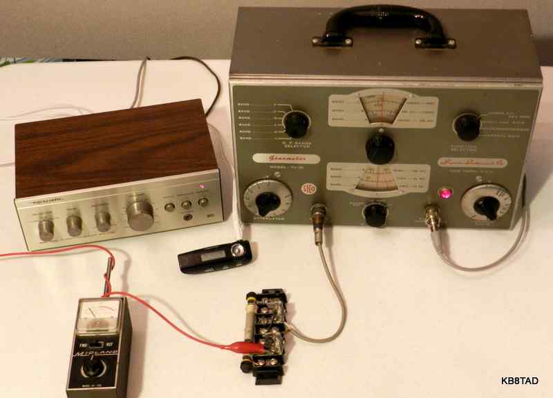
Fig 8 - Superior Instruments Genometer TV-50 as broadcaster. An MP3 player feeds a small Radio Shack audio amplifier. The modified signal generator feeds an external Pi network. The passive field strength meter from the CB era shows maximum signal on antenna at resonance. Pi network is adjusted to select the resonant frequency and maximize the signal.
Since I bypassed the attenuator resistors, the signal generator output had a higher impedance. I fed the RF output to a small external Pi network made from a broadcast ferrite antenna and a couple of trimmer capacitors to maximize the signal voltage at my frequency of choice and eliminate harmonics. (Fig 9)
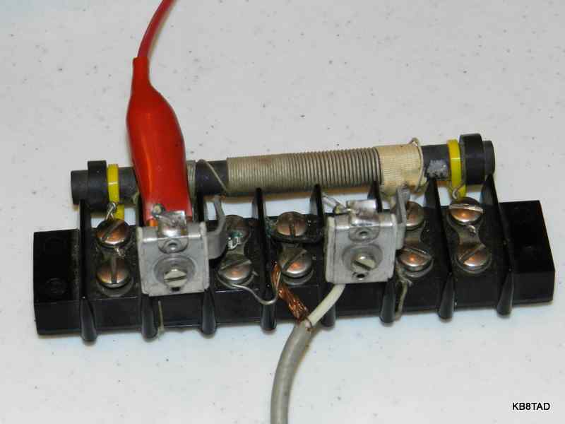
Fig 9 - Simple Pi network made of radio antenna coil with screwdriver-adjusted 50 to 500 picofarad trimmer caps on both sides to ground.
A simple L-network as described above with a loading coil and a parallel trimmer capacitor would probably have worked as well. The result was an excellent broadcaster. Details and schematic for my TV-50 modifications can be found at the website link in the footnotes. For home brewers, the Antique Radio Forum has several broadcaster designs, primarily using dual control tubes. A link to a schematic and discussion is also in the footnotes.
I had read on the net of a modified Eico 315 signal generator re-purposed as a regenerative receiver. Since a regenerative receiver circuit can be viewed as a controlled oscillator, such conversion is possible. The positive feedback path for a regenerative receiver circuit is varied by an added control so that the circuit can be adjusted to just below the point of oscillation. At that point, the regenerative receiver has tremendous amplification and can receive AM if a radio signal is injected on the input grid by way of a small capacitor to an antenna. The set can also receive CW and SSB at just beyond the point of oscillation. I decided to convert a Superior TV-50A (a very different circuit from the TV-50 noted above). I added a potentiometer to control the screen voltage of the oscillator tube. The main problem I encountered was that the signal generator had too high a level of feedback. The feedback windings were designed to be optimal for an oscillator, not a regenerative radio. I tacked resistors across the feedback windings to limit the feedback level and was able to make the regenerative radio circuit work reasonably well for portions of two bands but the result was not that stable or smooth, probably because the feedback windings were still not optimal for a regenerative set. I have had better results with completely homebrew regenerative sets and abandoned that project. However I may go back to it and see if I can tame the circuit, possibly by reducing the B+ voltage. That's part of the fun of being a radio experimenter.
Let me know of your fun adventures with service-type signal generators. Send an e-mail to kb8tad (ATsymbol) gmail.com
--------------------
Details and schematic for modifying a Superior Genometer TV-50 as a part 15 broadcaster
Link to the discussion and schematic of the most recent version of the homebrew dual-control tube part 15 broadcaster on the Antique Radio Forum.
Date 12-08-13
An Allied SX-190 receiver was the previous project on the bench.