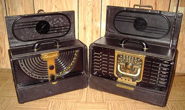
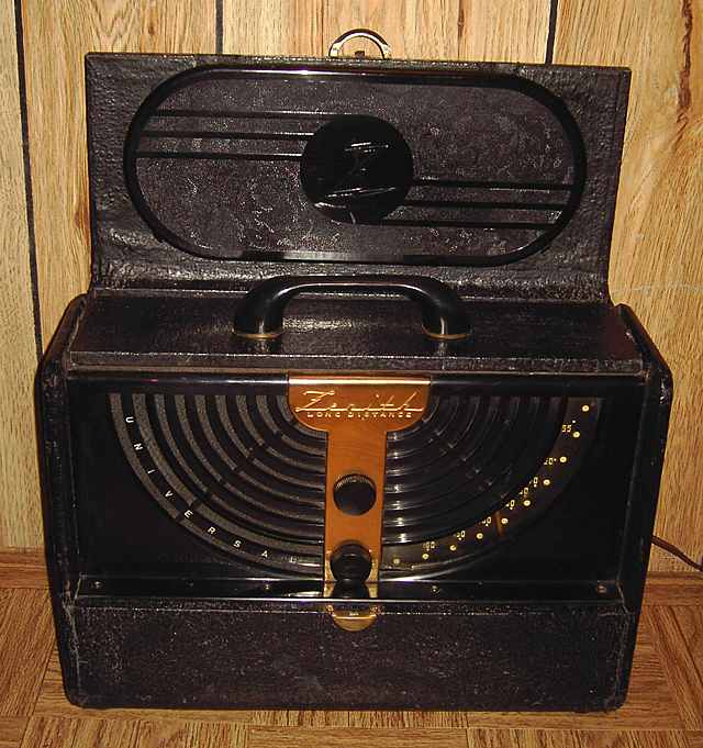
Zenith 6G001Y "Long Distance" 3-way portable
This Zenith 6G001Y "Long Distance" Universal (on the left) is a broadcast-only brother to the Zenith Transoceanic 8G005TZ1Y (on the right). Both are early postwar Zenith portables with loctal tubes.

Chassis number on this 6G001Y is 6C40, serial number T980025. The speaker is stamped with 49U512 which I assume is a date code. A schematic can be found in Rider volume 15, Zenith pages 30-31. These may be downloaded from Nostalgiaair. See the home page for the Nostalgiaair URL.
Repairs
Contact cleaner was used on the tube pins and sockets. Three of the tubes were dead with open filaments. Those were replaced and the filament line was checked for continuity and possible shorts. The power cord was replaced.
The set had been repaired earlier in its long life. As always, I test the circuitry with an ohmmeter before applying power. The chassis-mounted dropping resistor (two sections of 950 ohms each) which feeds the tube filament chain from the 110 volts B+ had been replaced with a similar two-section resistor. One section of that replacement was open. The 140 ohm dropping resistor between the rectifier and the first electrolytic had been replaced with a pair of 5 watt resistors with bare leads uncomfortably close to other circuitry. The rectifier side of those resistors had a bad solder joint. All of these filament dropping resistors were slated for replacement but some rubber-covered wiring with flaking insulation and a couple of capacitors in that section of the chassis, including the 0.05 cap across the power line, needed to be replaced first. I attribute the dried and cracked wire insulation in that section of the chassis at least partly to the heat of the filament dropping resistors and to the 117Z6GT rectifier tube. The rectifier tube itself consumes nearly 10 watts given off as heat, more power than all the rest of the set. The power resistors consume about 5 watts, given off as heat. After replacing some wiring and the capacitors in that section of the chassis, I replaced the chassis-mounted resistor piece with a terminal strip and two 1000 ohm power resistors (an extra 100 ohms over the original).
The audio coupling and AVC caps were also replaced. The electrolytic caps were tested and found to be in good condition.
I fed the filament chain with a variable low voltage source and checked the voltage drop across each tube filament to locate any possible remaining shorts. Voltage drops across each of the filaments were fine. Tube data indicate a typical operating voltage of 2.8 volt for the 3Q5 audio output tube and 1.4 volts for each of the other battery tubes for a total of 8.4 volts. I prefer a bit less voltage for longer tube life. About 7.7 to 8.0 volts allows for a bit of margin.
Power up tests
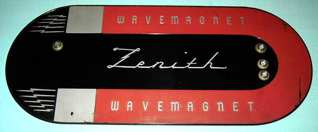
I connected the chassis to the wavemagnet antenna with clipleads. I first used my Heathkit PS-4 high voltage regulated power supply to feed DC to the set, positive to the cathode connection of the rectifier and negative to the return side of the power cord. This enabled testing of the filament dropping resistors that I had replaced. I brought the voltage up slowly while monitoring current and the voltage on the filament chain. The set began playing as the voltage input approached 100 volts DC and the filament chain showed 7.4 volts. I followed up with a variac and the 117Z6GT rectifier. With the extra 100 ohms I had added to the filament resistors, the filament chain read 7.9 volts with 120 volts AC input. The radio played quite well at that level, a good compromise allowing for some margin in case the local line voltage rises to 125 or falls to 115.
IF alignment was accurate but tweaking the converter and RF trimmers made a major difference. Sensitivity after tweaking was excellent, on a par with the broadcast band sensitivity I have come to expect of the Transoceanic.
date 4-30-07, update 3-21-11
A Kepco 605 Regulated Power Supply was the previous item on the bench.