Chapter 4d - Ideal Adiabatic Solution - The D-90
Ross Yoke-drive Engine
The 90 cc D-90 engine is fully described in Andy
Ross' fascinating book Making
Stirling Engines (pages 41 - 45). At Ohio
University we have a laboratory
model of the D-90 Yoke drive engine which
is heated electrically in order to accurately determine the heat
power input. In this section we examine the results of performing an
Ideal Adiabatic simulation of the D-90 engine under specific typical
operating conditions as follows
Mean operating
pressure - pmean = 2 bar.
(The crankcase is sealed, and the
output shaft power is obtained by a magnetic coupling. Andy
typically pressurizes the crankcase with a bicycle pump to about 2
bar.)
Cooler temperature 27
degrees Celsius (300 K), and heater temperature 650 degrees Celsius
(923 K)
Operating frequency 50 Hz. (Note that the Ideal
Adiabatic model is independent of operating speed - all results are
presented per cycle)
In order to simulate the engine by means of the Ideal
Adiabatic model equation set given
previously, we require the equations for the Yoke-drive
volume variations and derivatives Vc, Ve,
dVc and dVe
(all functions of crank angle θ), as well as the void volumes of the
heat exchangers Vk, Vr, and Vh.
The cyclic convergence behavior of the Ideal
Adiabatic model is extremely good, and using 360 increments over the
cycle, the system effectively converges within 5 cycles. The
convergence criterion chosen is that after a complete cycle both
variable temperatures Te and Tc must be within one degree Kelvin of
their initial values. We now consider the solution of the temperature
variables Tc and Te, the heat energy variables Qk, Qr, Qh, and the
work energy variables Wc, We, and the net work done W. These results
are presented as plots showing the variation of these parameters with
the crank angle θ.

In
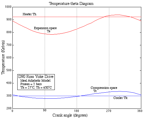
the temperature-theta diagram we observe a large cyclic temperature
variation of the gas in the expansion space (> 100 K), its mean
value being less than that of the heater temperature of 923 K.
Similarly the mean gas temperature in the compression space is higher
than the coller temperature. This suggests that the adiabatic working
spaces effectively reduce the temperature limits of operation, thus
reducing the thermal efficiency to less than that of the Carnot
efficiency.

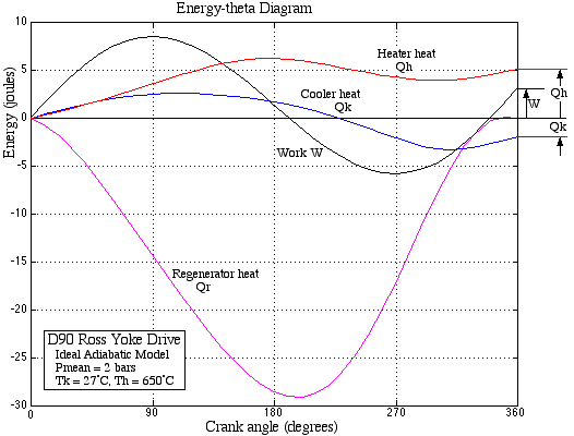
The
energy-theta diagram shows the accumulated heat transferred and work
done over the cycle. Notice that the work done W starts with the
(positive slope) expansion process then the compression process, and
again returning to the expansion process, Thus the total work
excursion is almost 15 joules, however the net work done at the end
of the cycle is only 3 joules. The most significant aspect of the
energy-theta diagram is the considerable amount of heat transferred
in the regenerator over the cycle, almost ten times that of the net
work done per cycle. This tends to indicate that the engine
performance depends critically on the regenerator effectiveness and
its ability to accomodate high heat fluxes. This aspect will be
revisited in the section on the Simple
analysis, when we examine the effect of
imperfect heat exchangers on Stirling engine performance.
Significantly the energy rejected by the gas to the regenerator
matrix in the first half of the cycle is equal to the energy absorbed
by the gas from the matrix in the second half of the cycle, thus the
net heat transfer to the regenerator over a cycle is zero. It is for
this reason that the importance of the regenerator was not understood
for about 100 years after Stirling's original patent describing the
function and importance of the regenerator. The Lehmann machine on
which Schmidt did his analysis was apparently not fitted with a
regenerator, and it is conceivable that Schmidt did not appreciate
its importance, He refers to the textbook by Zeuner as containing a
"complete, simple and clear theory" of air engines, but in
the same textbook Zeuner decries the use of regenerators for air
engines (Finkelstein, T., 1959, Air Engines
in The Engineer part
1, 27 March.)
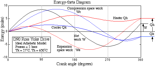
It is of interest to examine the two components, Wc
and We, which added together gives the net work done W. These are
shown as dashed lines in the following diagram.

Notice
in particular that the expansion space work done (We) undergoes a
vastly different process from that of heat transferred to the heater
(Qh), however at the end of the cycle they have equal values (Qh =
We). Similarly for the compression space work done (Wc) and the heat
transferred to the cooler (Qk). In retrospect this must be so in
order to retain an energy balance, however it did catch us unawares
and surprised us when we first noticed this. The ideal regenerator
thus behaves as the perfect isolator, isolating the energy balance of
the heater and expansion space from that of the cooler and
compression space. Thus for the Ideal Adiabatic model over a complete
cycle
Qh = We; (Qe = 0)
Qk = Wc; (Qc = 0)
W
= Wc + We
Recall that for the Ideal Isothermal model
Qe = We; (Qh = 0)
Qc = Wc; (Qk = 0)
W
= Wc + We
Furthermore the Ideal Adiabatic model in itself does
not give results which are significantly different from those of the
Ideal Isothermal model. The pressure-volume diagram is of similar
form, and the power output and efficiency are quantitatively similar
(albeit the efficiency of the Ideal Adiabatic model is about 10%
lower for reasons described above). However the the behaviour of the
Ideal Adiabatic model is more realistic, in that the various results
are consistent with the expected limiting behavior of real machines.
Thus the heat exchangers become necessary components without which
the engine will not function. The required differential equation
approach to solution reveals the considerable amount of heat
transferred in the regenerator, indicating its importance in the
cycle, and provides a natural basis for extending the analysis to
include non-ideal heat exchangers (Simple
analysis). Thus the solution of the Ideal
Adiabatic model equations is equivalent to a simulation of the engine
behavior in all respects, from setting up the initial conditions
until convergence to cyclic steady state is attained. Throughout this
process all the variables of the system are available as by-products
of the simulation and can be used for extending the analysis. Thus
for example the mass flow rates through all the heat exchangers can
be used in order to evaluate the heat transfer and flow friction
effects over the cycle.
______________________________________________________________________________________

Stirling Cycle Machine Analysis by Israel
Urieli is licensed under a Creative
Commons Attribution-Noncommercial-Share Alike 3.0 United States
License


